Ultrahigh-frequency RFID anti-metal tag antenna based on microstrip structure

An anti-metal tag, ultra-high frequency technology, applied in the direction of antenna, antenna parts, radiation element structure, etc., can solve the problems of complex processing, high cost, narrow frequency band, etc., to reduce the actual size, widen the bandwidth, good Effect of Broadband Characteristics

Active Publication Date: 2021-08-20
NINGBO UNIV
View PDF14 Cites 1 Cited by
  • Summary
  • Abstract
  • Description
  • Claims
  • Application Information

AI Technical Summary

Problems solved by technology

However, the ultra-high frequency RFID anti-metal tag antenna based on the microstrip structure usually needs to use metal vias, short-circuit patch

Method used


Image

  • Ultrahigh-frequency RFID anti-metal tag antenna based on microstrip structure
  • Ultrahigh-frequency RFID anti-metal tag antenna based on microstrip structure
  • Ultrahigh-frequency RFID anti-metal tag antenna based on microstrip structure

Examples


Embodiment

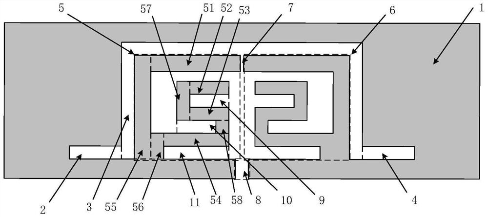
[0014] Example: such as figure 1As shown, a UHF RFID anti-metal tag antenna based on a microstrip structure includes a dielectric substrate and a radiation module arranged on the dielectric substrate. The dielectric substrate is a rectangular plate, and the radiation module is realized by a microstrip structure. The radiation module includes a radio frequency Chip, metal layer 1, first rectangular groove 2, second rectangular groove 3, third rectangular groove 4, first radiation unit 5 and second radiation unit 6, metal layer 1 is attached to the upper surface of the dielectric substrate, metal layer 1 The front end of the metal layer 1 is flush with the front end of the dielectric substrate, the rear end of the metal layer 1 is flush with the rear end of the dielectric substrate, the left end of the metal layer 1 is flush with the left end of the dielectric substrate, and the right end of the metal layer 1 is flush with the dielectric substrate. The right end surface of the s...


PUM

PropertyMeasurementUnit
Thicknessaaaaaaaaaa
Lengthaaaaaaaaaa
Lengthaaaaaaaaaa

Abstract

The invention discloses an ultrahigh-frequency RFID anti-metal tag antenna based on a microstrip structure. The antenna comprises a dielectric substrate and a radiation module arranged on the dielectric substrate, the dielectric substrate is a rectangular plate, and the radiation module is realized by adopting the microstrip structure. The radiation module comprises a radio frequency chip, a metal layer, a first rectangular groove, a second rectangular groove, a third rectangular groove, a first radiation unit and a second radiation unit, the first radiation unit and the second radiation unit are respectively composed of eight rectangular metal blocks, and the first radiation unit and the second radiation unit form a symmetrical oscillator antenna structure; and the first radiation unit and the second radiation unit form a U-shaped groove communicated with the first rectangular groove and the third rectangular groove, and a gap formed between the first radiation unit and the second radiation unit and a gap in the first radiation unit and the second radiation unit form an impedance adjusting structure. The antenna has the advantages of being long in reading distance, high in gain, small in size, simple in processing technology, low in cost and wide in frequency band.

Description

technical field [0001] The invention relates to an ultra-high frequency RFID anti-metal tag antenna, in particular to an ultra-high frequency RFID anti-metal tag antenna based on a microstrip structure. Background technique [0002] With the promotion of Internet of Things technology in various fields, the application scenarios of radio frequency identification technology (RFID) tags are becoming more and more diverse. Some applications require RFID tag antennas to be installed on items of different materials, such as glass, wood, or even metal. RFID tag antennas are usually attached directly to the object that needs to be identified, and metal objects are very challenging for RFID tag antennas. When an ordinary RFID tag antenna is placed on the surface of a metal object, the radiation resistance of the RFID tag antenna will drop sharply due to the electromagnetic wave’s characteristic of metal reflection. At this time, the original performance indicators of the RFID tag ant...

Claims


Application Information

Patent Timeline
IPC IPC(8): H01Q1/22H01Q1/38
CPCH01Q1/2225H01Q1/38
Inventor 王健陈德怀时稳霍建建
Owner NINGBO UNIV
Why Eureka
Try Eureka