

Multifunctional integrated antenna
An integrated and multi-functional technology, applied in the field of communication, can solve the problems of waste of manpower, low degree of commonality and modularization, and incomplete functions, etc., to improve the degree of commonality and modularization, improve directionality and sensitivity, The effect of meeting multi-functional needs
- Summary
- Abstract
- Description
- Claims
- Application Information
AI Technical Summary
Problems solved by technology
Method used
Image

Examples
Embodiment Construction
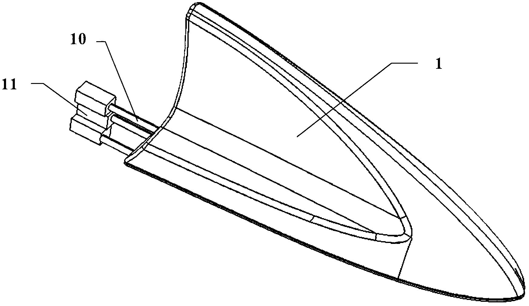
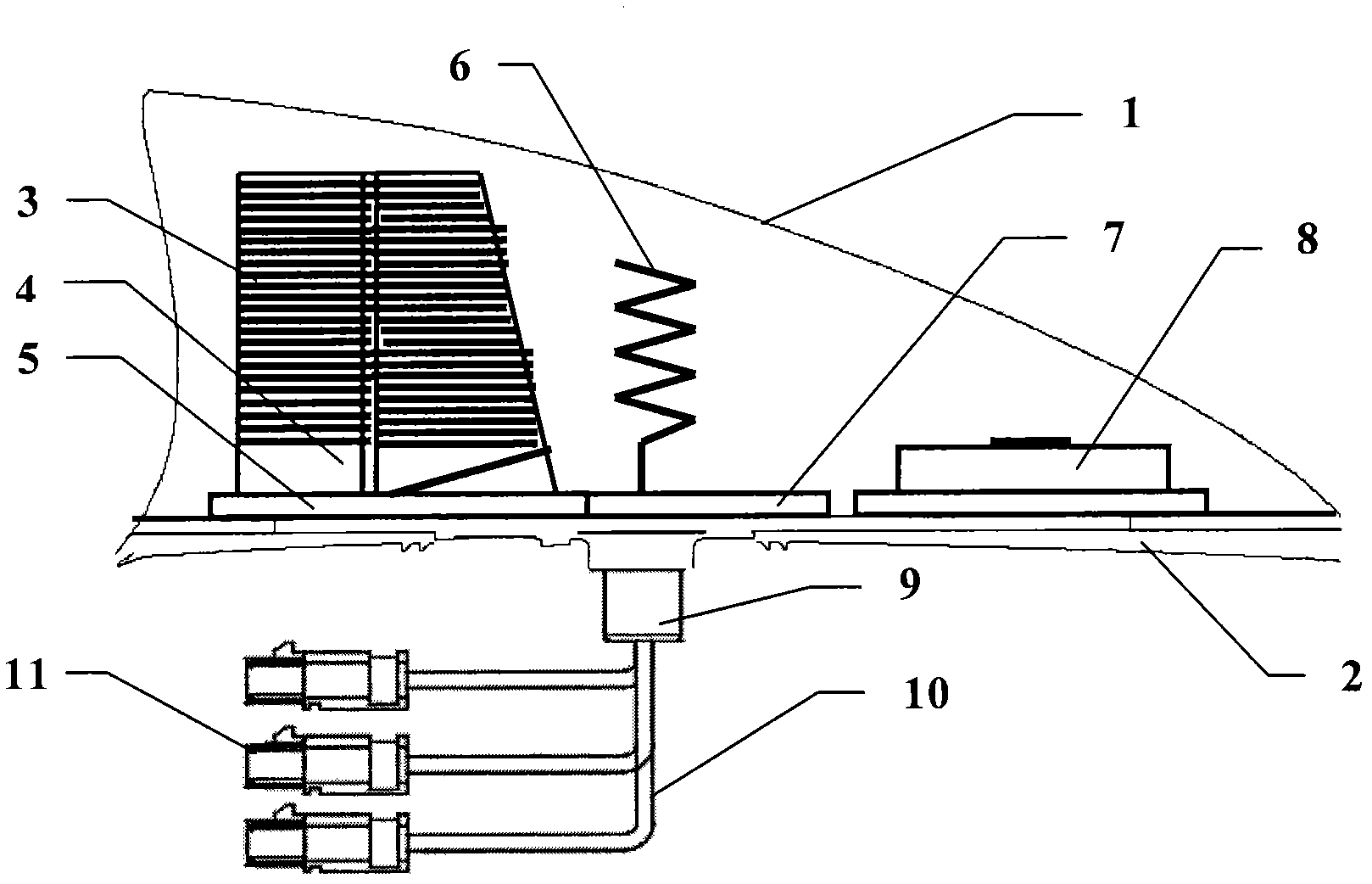
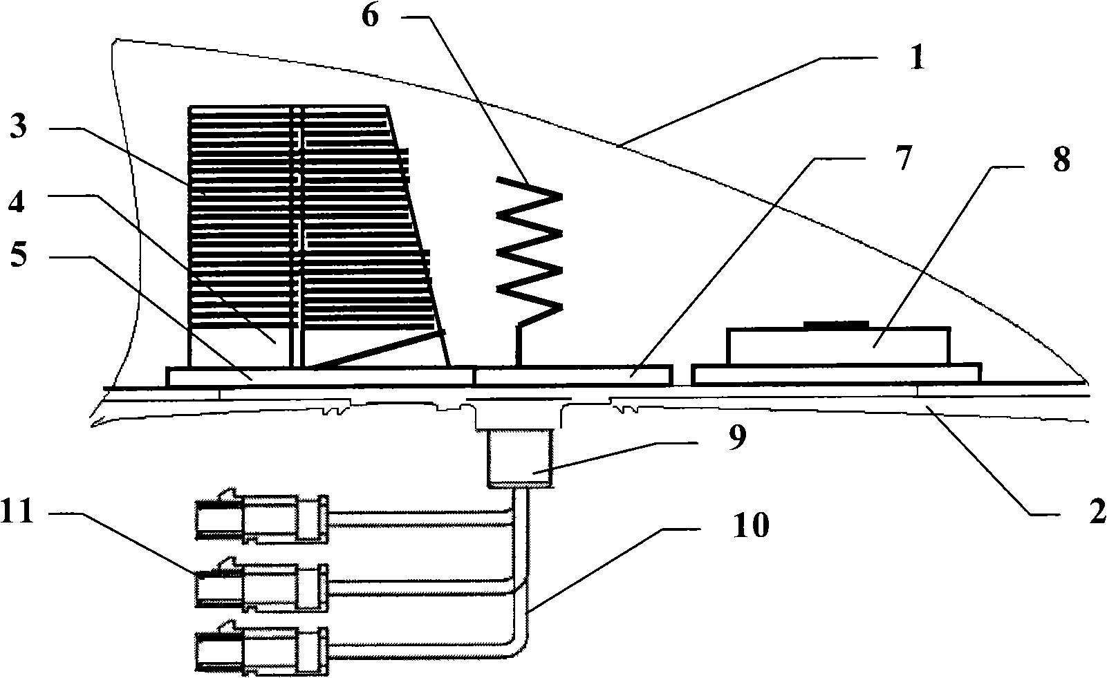
[0034] Please also refer to figure 1 and figure 2 , which schematically show the internal and external structures of a preferred embodiment of the multifunctional integrated antenna of the present invention. As shown in these figures, the multifunctional integrated antenna mainly includes a housing 1, a base 2, a first antenna module, a second antenna module and a third antenna module, and these components will be described in detail below in conjunction with the accompanying drawings. In order to be able to understand more clearly their structural features, advantages and functions realized.
[0035] In this preferred embodiment, the housing 1 is covered on the base 2, and the shape of the housing 1 is preferably set to be fish-like or hemispherical, which will make the overall dimensions of the multifunctional integrated antenna more compact. According to the layout requirements of the internal antenna module, it is generally suitable to set the size of the housing 1 to ...
PUM
 Abstract
Description
Claims
Application Information