A reflector based on ultra-wide stopband frequency selective surface
A technology of frequency selective surface and reflector, which is applied in the field of communication, can solve the problem of narrow stop band on the surface, and achieve the effect of strong electromagnetic wave transmission, good transmission effect, and widened stop band bandwidth
- Summary
- Abstract
- Description
- Claims
- Application Information
AI Technical Summary
Problems solved by technology
Method used
Image
Examples
Embodiment 1
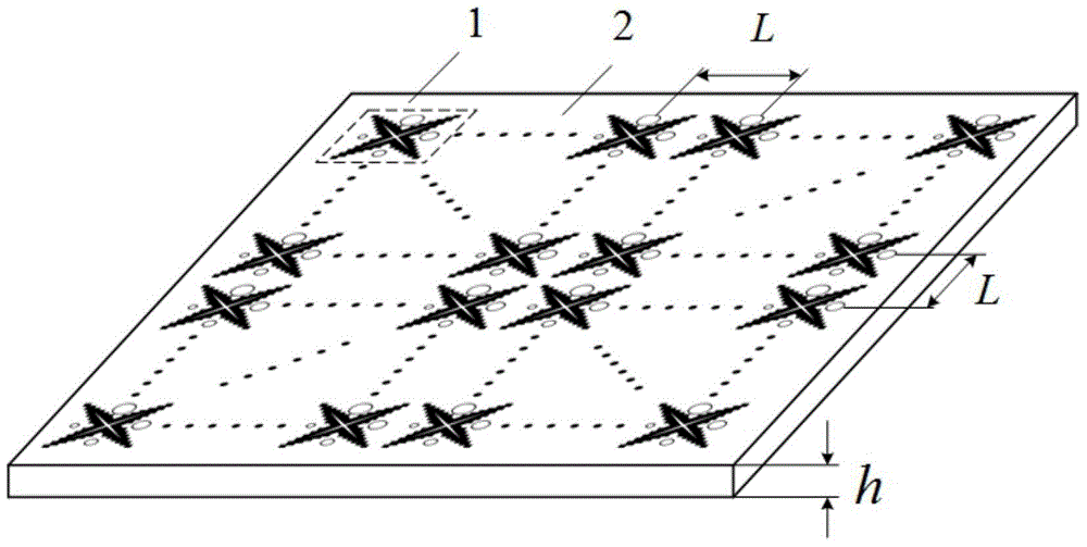
[0043] Embodiment 1: The reflector of the present invention is composed of 20×20 frequency selective surface units 2 printed on the dielectric substrate 2, and the 20×20 frequency selective surface units are arranged periodically along the X and Y axis directions where they are located. cloth, the working frequency of which is 1.7GHz-6.1GHz, wherein the distance between the centers of adjacent reflector units is L=20mm.
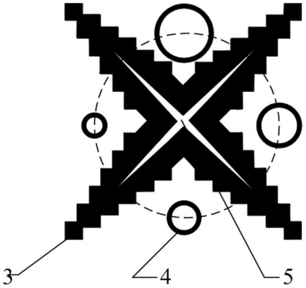
[0044] The frequency selective surface unit 1 includes a zigzag shuttle-shaped cross patch 3 and a ring patch 4. The zigzag shuttle-shaped cross patch 3 is provided with a four-pointed star gap 5, and the centers of the two overlap, and the four-pointed star gap 5 The four corners of the four corners are in the same direction as the four arms of the zigzag shuttle-shaped cross patch 3; the number of the ring patches 4 is set to four, and the four ring patches are respectively located 3. In the middle of the two adjacent arms, they are arranged clockwise or co...
Embodiment 2
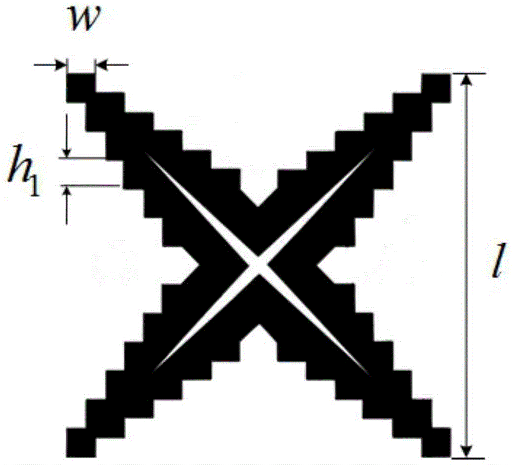
[0049] Embodiment 2: The design principle, technology and scheme of this embodiment are the same as those of Embodiment 1. The reflector of this embodiment is composed of 20×20 frequency selective surface units 2 printed on the dielectric substrate 2. The 20×20 The frequency selective surface units are arranged periodically along the X and Y axis directions where they are located, and the center-to-center distance between adjacent reflector units is l=20mm; the dielectric substrate 2 adopts a FR4 square plate with a thickness of h=3mm, and the FR4 material is ε r The dielectric material of =4.4; the distance between the vertices of two adjacent arms of the jagged shuttle-shaped cross 3 is l=19mm.
[0050] Compared with Example 1, the following relevant parameters have been adjusted, the sawtooth width is w=1.8mm, and the sawtooth height h 1 = 1.17 mm. The outer radius r of the largest ring 1 =2mm, t=0.6, then the outer radii of the other three rings are r 2 = 1.2 mm, r 3 =...
Embodiment 3
[0051] Embodiment 3: The design principle, technology and scheme of this embodiment are the same as those of Embodiment 1. The reflecting plate of this embodiment is composed of 20×20 frequency selective surface units 2 printed on the dielectric substrate 2. The 20×20 The frequency selective surface units are arranged periodically along the X and Y axis directions where they are located, and the center-to-center distance between adjacent reflector units is l=20mm; the dielectric substrate 2 is a FR4 square plate with a thickness of h=3mm, and the FR4 material is ε r The dielectric material of =4.4; the distance between the vertices of two adjacent arms of the jagged shuttle-shaped cross 3 is l=19mm.
[0052] Compared with Example 1, the following relevant parameters have been adjusted, the sawtooth width is w=1.12mm, and the sawtooth height h 1 = 0.84 mm. The outer radius r of the largest ring 1 =2.6mm, t=0.9, then the outer radii of the other three rings are r 2 = 2.34mm, ...
PUM
 Abstract
Description
Claims
Application Information
 - R&D
- Intellectual Property
- Life Sciences
- Materials
- Tech Scout
- Unparalleled Data Quality
- Higher Quality Content
- 60% Fewer Hallucinations
Browse by: Latest US Patents, China's latest patents, Technical Efficacy Thesaurus, Application Domain, Technology Topic, Popular Technical Reports.
© 2025 PatSnap. All rights reserved.Legal|Privacy policy|Modern Slavery Act Transparency Statement|Sitemap|About US| Contact US: help@patsnap.com


