Heat exhaust system for on-aircraft electric generator

an electric generator and heat exhaust technology, which is applied in the direction of efficient propulsion technologies, machines/engines, turbine/propulsion fuel heating, etc., can solve the problems of increasing the size of the electric generator, increasing the heat generation capacity difficult to count on the fuel supplied to the gas turbine engine to serve as a heat release destination, etc., to achieve the effect of increasing the size of the electric generator, increasing the power generation capacity, and increasing the heat generation amoun

Active Publication Date: 2021-02-09
IHI CORP
View PDF21 Cites 1 Cited by
  • Summary
  • Abstract
  • Description
  • Claims
  • Application Information

AI Technical Summary

Benefits of technology

[0007]As the equipment installed in the aircraft including the above-mentioned gear pump are increasingly electrified, the aircraft will need to carry a large-size electric generator with a higher power generation capacity. An increase in size of the electric generator results in a larger amount of heat generation by the electric generator. Accordingly, an amount of heat to be released into the fuel, the air at the outlet of the fan, and the like by the intermediary of the engine oil is increased as well.
[0008]In the meantime, the fuel supplied to the gas turbine engine is on the decrease thanks to an improvement in fuel efficiency of the gas turbine engine. Reduction in fuel supply to the gas turbine engine decreases a thermal capacity per unit time of the supplied fuel that serves as a coolant. Accordingly, in view of further improvements in fuel efficiency of the gas turbine engines in the future, it will be difficult to count on the fuel supplied to the gas turbine engine to serve as a destination of heat release for the additional heat attributed to the larger amount of heat generation of the electric generator increased in size.

Problems solved by technology

An increase in size of the electric generator results in a larger amount of heat generation by the electric generator.
Accordingly, in view of further improvements in fuel efficiency of the gas turbine engines in the future, it will be difficult to count on the fuel supplied to the gas turbine engine to serve as a destination of heat release for the additional heat attributed to the larger amount of heat generation of the electric generator increased in size.

Method used


Image

  • Heat exhaust system for on-aircraft electric generator
  • Heat exhaust system for on-aircraft electric generator

Examples


Embodiment Construction

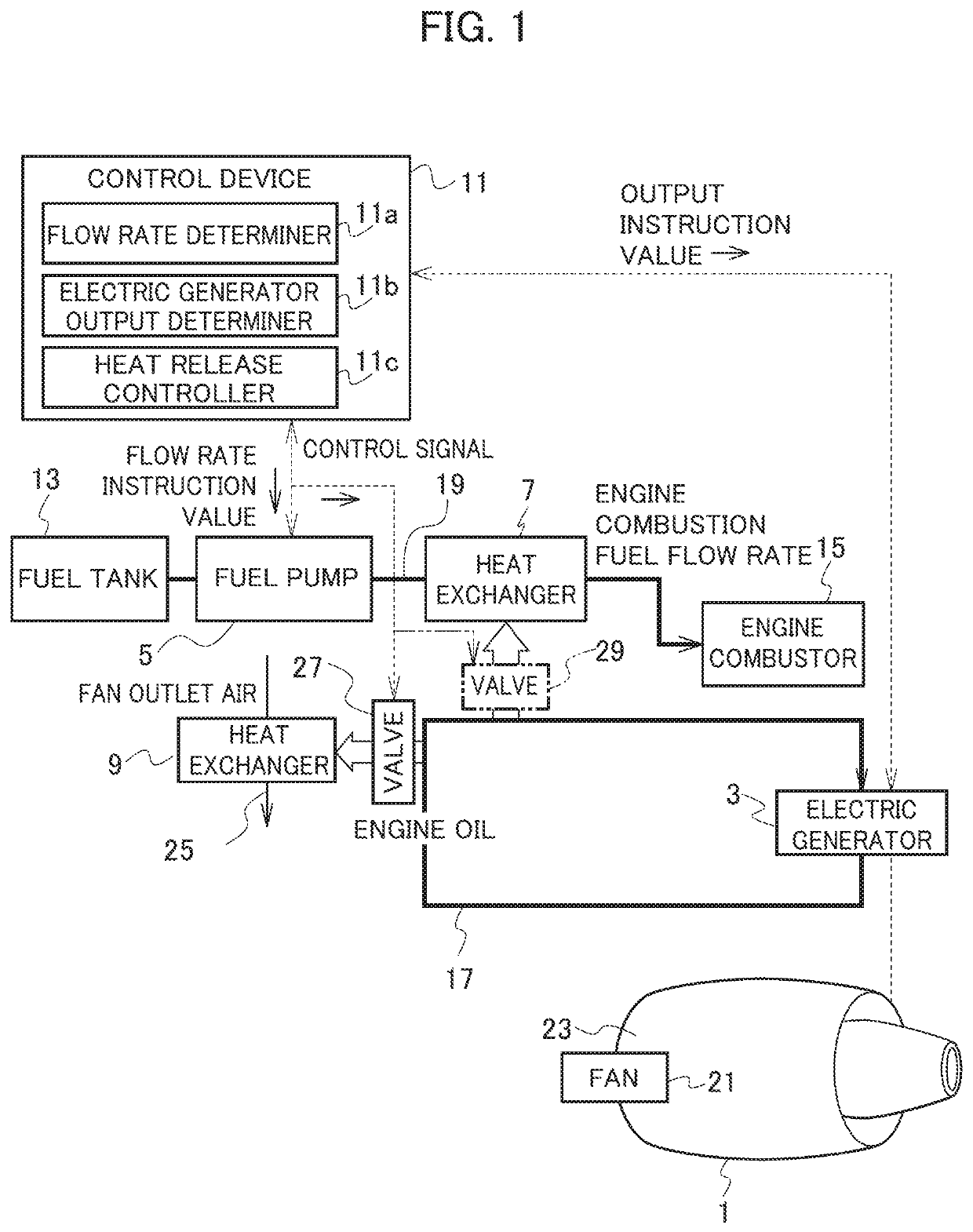
[0013]An embodiment of this disclosure will be described below with reference to a drawing.

[0014]A heat exhaust system of this embodiment shown in FIG. 1 is configured to release heat generated by an electric generator 3 that is installed in an aircraft and directly connected to a gas turbine engine 1 thereof. The heat exhaust system includes a fuel pump 5, two heat exchangers 7 and 9, and a control device 11.

[0015]The fuel pump 5 is a variable-flow electric metering pump which supplies fuel in a fuel tank 13 to an engine combustor 15 of the gas turbine engine 1. The fuel pump 5 can perform variable control of flow rate of the fuel supplied from the fuel tank 13 to the engine combustor 15 so as not to supply excess fuel that exceeds a flow rate required for combustion in the engine combustor 15.

[0016]Unlike the gear pump that has conventionally been used as a metering pump, the fuel pump 5 is driven by electric power generated by the electric generator 3. Specifically, the power to ...


PUM


Abstract

A heat exhaust system for an on-aircraft electric generator, includes: a fuel pump which is driven by electric power generated by an electric generator installed in an aircraft, and which measures and supplies fuel to an engine of the aircraft; a first heat exchanger which releases heat generated by the electric generator into the fuel supplied to the engine; a fuel flow rate determiner which determines a flow rate of the fuel supplied to the engine by the fuel pump; an electric generator output determiner which determines an output from the electric generator; and a heat release controller which controls heat release at the first heat exchanger by using at least one of the flow rate of the fuel determined by the fuel flow rate determiner and the output determined by the electric generator output determiner as a control parameter.

Description

CROSS REFERENCE TO RELATED APPLICATIONS[0001]This application is a continuation application of International Application No. PCT / JP2017 / 005398, filed on Feb. 15, 2017, which claims priority to Japanese Patent Application No. 2016-170772, filed on Sep. 1, 2016. The contents of these applications are incorporated herein by reference in their entirety.BACKGROUND1. Technical Field[0002]This disclosure relates to a heat exhaust system for an on-aircraft electric generator.2. Description of the Related Art[0003]An electric generator to generate electric power to be supplied to electric equipment is installed in an aircraft. The electric generator is driven by power transmitted from a gas turbine engine through an accessory gear box for driving auxiliary machines. The heat generating electric generator is cooled by engine oil, and the heat of the engine oil is released at a heat exchanger into fuel supplied from a fuel tank to the gas turbine engine, into air at an outlet of a fan of the g...

Claims


Application Information

Patent Timeline
Patent Type & Authority Patents(United States)
IPC IPC(8): F02C7/224F02C7/32F02C7/16
CPCF02C7/224F02C7/16F02C7/32F05D2260/213B64D33/08B64D41/00F05D2220/76F05D2260/232Y02T50/60
Inventor MORIOKA, NORIKOOYORI, HITOSHI
Owner IHI CORP
Why Eureka
Try Eureka