

Drain valve of drainage bag
A drainage valve and drainage bag technology, which is applied to wound drainage devices, valves, suction devices, etc., can solve the problems of drainage valve outlet pollution, switch touch parts are easily polluted by drainage fluid, and interact with each other, so as to avoid pollution , Reduce the possible effect of retrograde infection and infectious disease
- Summary
- Abstract
- Description
- Claims
- Application Information
AI Technical Summary
Problems solved by technology
Method used
Image

Examples
Embodiment 1
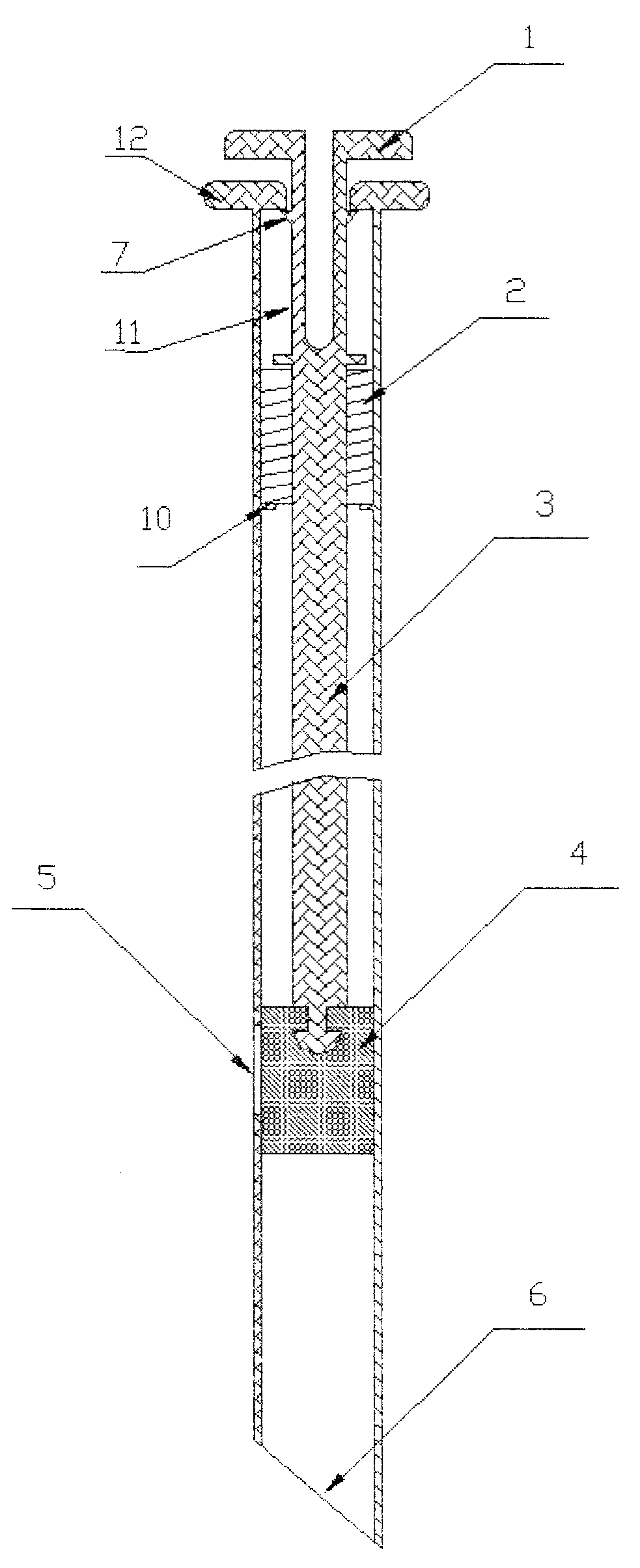
[0040] like Figure 1-4 As shown, the present invention includes a valve casing and a liquid discharge port 6 below; the side wall of the valve casing is provided with a liquid inlet 5 leading to the inside of the valve casing; the switch touch part 1 is connected to the lower closing member 4 through the transmission mechanism 3 .
[0041] In the actual working process, only need to manually operate the switch touch part 1 to realize the back and forth movement of the closure member 4, so as to realize the opening and closing of the liquid inlet 5 manually.
Embodiment 2
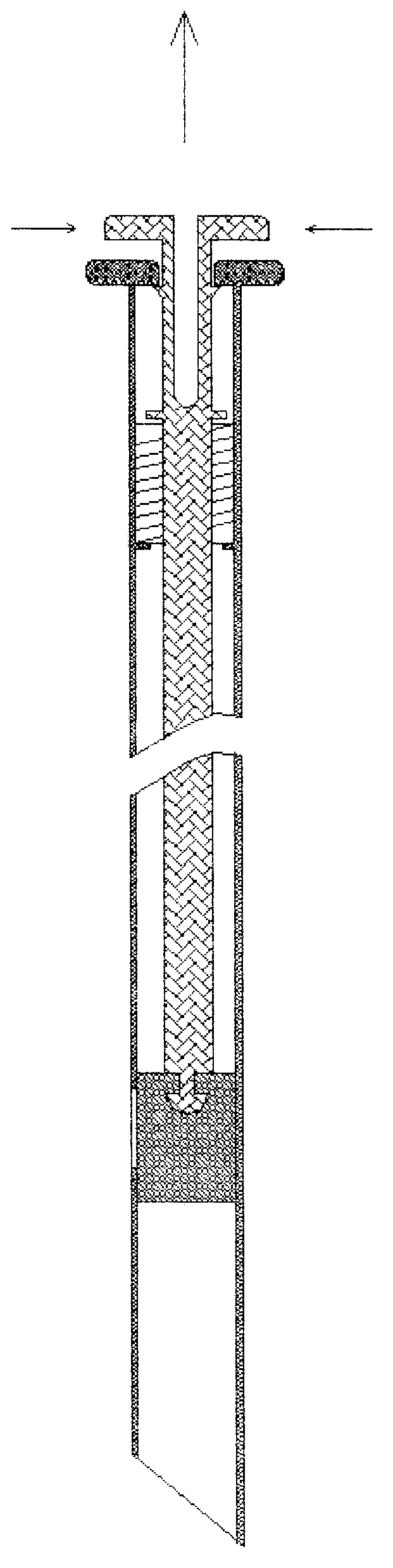
[0043] like Figure 1-4As shown, the present invention includes a valve casing and a liquid discharge port 6 below; the side wall of the valve casing is provided with a liquid inlet 5 leading to the inside of the valve casing; the switch touch part 1 is connected to the lower closing member 4 through the transmission mechanism 3 . The transmission mechanism 3 is a transmission rod, and an elastic reset mechanism 2 for storing elastic potential energy is installed between the transmission mechanism 3 and the valve casing. The switch touch part 1 is a squeeze or press or rotary switch or any combination thereof.
[0044] In the actual working process, the staff only needs to squeeze or press or rotate or any combination of them to release the elastic potential energy stored in the elastic reset mechanism 2, so that the switch touch part 1 drives the transmission mechanism 3 and the closure 4 Move upwards to realize the opening of the liquid inlet 5.
Embodiment 3
[0046] Such as Figure 1-4 As shown, the present invention includes a valve casing and a liquid discharge port 6 below; the side wall of the valve casing is provided with a liquid inlet 5 leading to the inside of the valve casing; the switch touch part 1 is connected to the lower closing member 4 through the transmission mechanism 3 . An elastic return mechanism 2 for storing elastic potential energy is installed between the transmission mechanism 3 and the valve casing. The switch touch part 1 is a squeeze or press or rotary switch or any combination thereof.
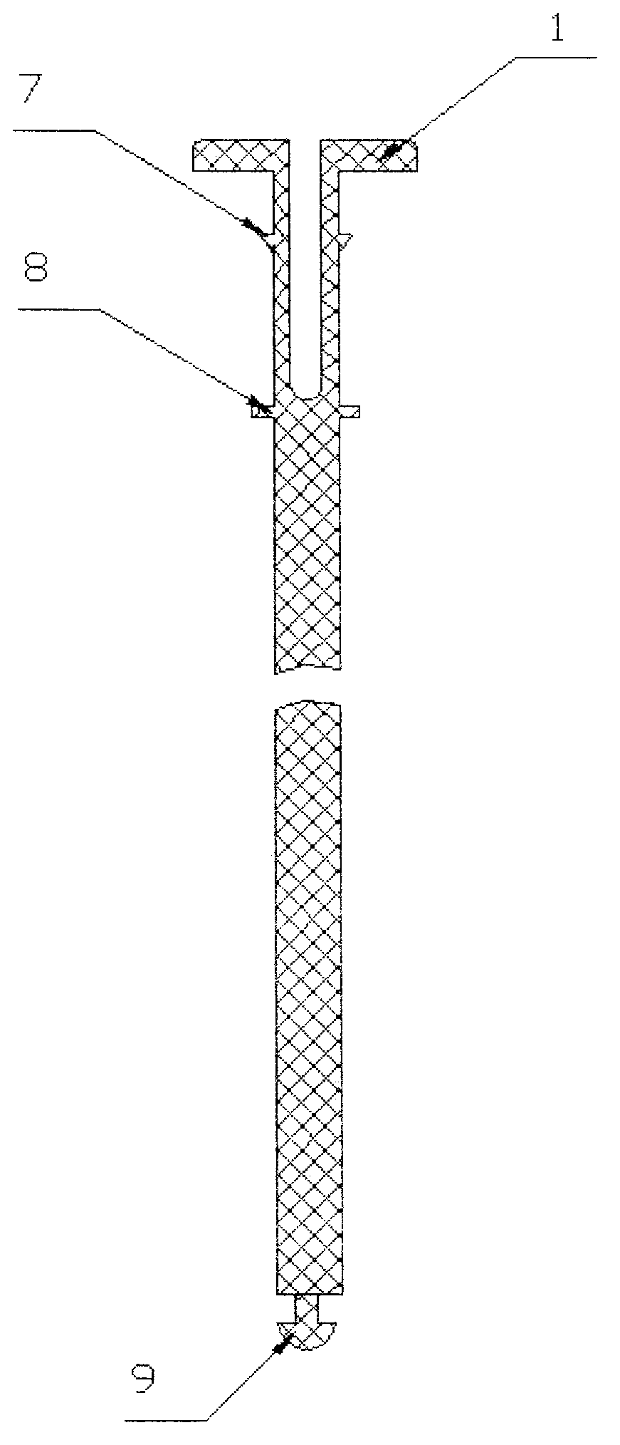
[0047] The switch touch part 1 and the transmission mechanism 3 are integrated; the switch touch part 1 is provided with a U-shaped opening for opening and closing movement, and the outer surface of the switch touch part 1 is provided with a force ring 8.
[0048] The installation elastic reset mechanism 2 is installed in the installation chamber 11 of the valve housing, and one end of the elastic reset mechanism 2 i...
PUM
 Abstract
Description
Claims
Application Information