Illuminating structure

A light-emitting structure and light-guiding member technology, which is applied in the direction of electric light source, light source fixing, lighting device, etc., can solve the problems of increasing the production cost of the known backlight module, increasing the cost of circuit board material required for circuit board width, etc.

Inactive Publication Date: 2012-12-26
AU OPTRONICS CORP
View PDF7 Cites 2 Cited by
  • Summary
  • Abstract
  • Description
  • Claims
  • Application Information

AI Technical Summary

Problems solved by technology

As a result, the requirement for the width of the circuit board is often larger, resulting in an increase in the material cost of the circuit board, thereby increasing the production cost of the known backlight module.

Method used


Image

  • Illuminating structure
  • Illuminating structure
  • Illuminating structure

Examples


Embodiment Construction

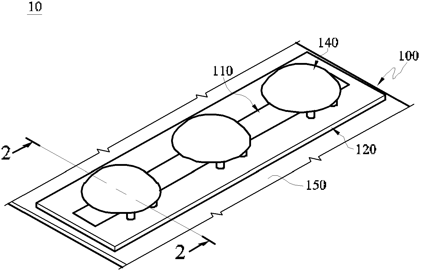
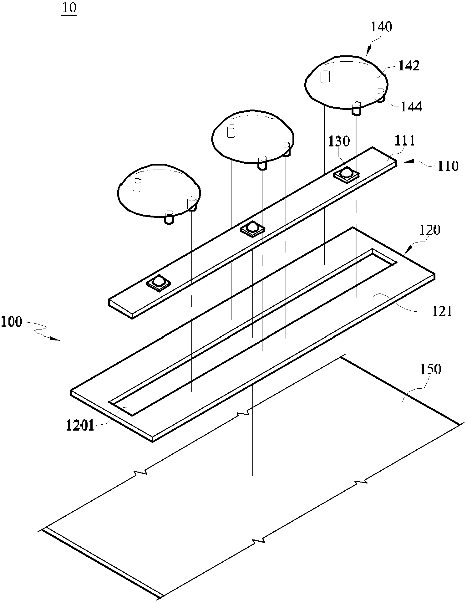
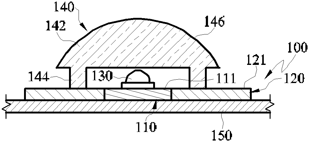
[0036] Please refer to Figure 1A , Figure 1B and figure 2 , Figure 1A It is a structural combination diagram of a light emitting structure according to an embodiment of the present invention, Figure 1B is a partially exploded view of a light emitting structure according to an embodiment of the present invention, figure 2 based on Figure 1A Sectional view of the 22 section line.

[0037] The light emitting structure 10 of this embodiment can be applied to a backlight module (not shown) of a display device (not shown), but not limited thereto. For example, the light emitting structure 10 of this embodiment can also be applied to lighting equipment in other fields.

[0038] The light emitting structure 10 includes a substrate assembly 100 , at least one light source 130 and at least one light guide member 140 . The illustration of this embodiment takes three light sources 130 and three light guide members 140 as examples, but the numbers of the light sources 130 and th...


PUM


Abstract

The invention provides an illuminating structure comprising a substrate component, at least a light source, and at least a light guiding member. The substrate component comprises a circuit board and a fixing board. The circuit board is provided with a surface, and is enclosed by the fixing board. The light source is disposed on the surface, and the light guiding member is disposed on the light source. The light guiding member is provided with a body and a plurality of supporting legs extending from one side of the body. The supporting legs are disposed on the fixing board, and the light source is disposed between the circuit board and the light guiding member. By using the illumination structure, the size of the circuit board can be reduced, the material costs of the circuit board can be reduced, therefore the production costs of the backlight module can be reduced.

Description

technical field [0001] The present invention relates to a light emitting structure, in particular to a light emitting structure with a light guiding member. Background technique [0002] The rapid progress of the multimedia society is mostly benefited from the rapid development of semiconductor devices or display devices. As far as display components are concerned, cathode display tubes (or called image tubes, Cathode Ray Tube, CRT) have been monopolizing the display market due to their excellent display quality and economy. However, CRTs have the problems of being too large and consuming too much energy. For the requirements of high image quality, low power consumption, thin mass production, low voltage drive, and small size, CRT-type displays obviously cannot meet these requirements. In view of this, liquid crystal display (Liquid Crystal Display, referred to as LCD) will have great advantages, and LCD has been widely used in medium and small portable TVs, video phones, c...

Claims


Application Information

Patent Timeline
Patent Type & Authority Applications(China)
IPC IPC(8): F21S2/00F21V17/00
Inventor 张继圣林苏逸杨承勋
Owner AU OPTRONICS CORP
Why Eureka
Try Eureka