Variable optical attenuator

An optical attenuator and modulation technology, applied in optics, instruments, nonlinear optics, etc., can solve problems such as optical path changes, surface tilt, and optical signal attenuation

Inactive Publication Date: 2003-12-31
BROWAVE CORP
View PDF2 Cites 3 Cited by
  • Summary
  • Abstract
  • Description
  • Claims
  • Application Information

AI Technical Summary

Problems solved by technology

[0004] Another known variable optical attenuator can be seen in US Patent No. 6,285,504. Its structure is to attach a reflector to an elastic material with a high thermal expansion coefficient. When the temperature changes, the elastic material with a high thermal expansion coefficient will The resulting deformation causes the surface of the mirror to tilt, causing the light path to change, resulting in attenuation of the optical signal
[0005] However, the structure of the above-mentioned known variable optical attenuator must be i

Method used


Image

  • Variable optical attenuator
  • Variable optical attenuator
  • Variable optical attenuator

Examples


Embodiment Construction

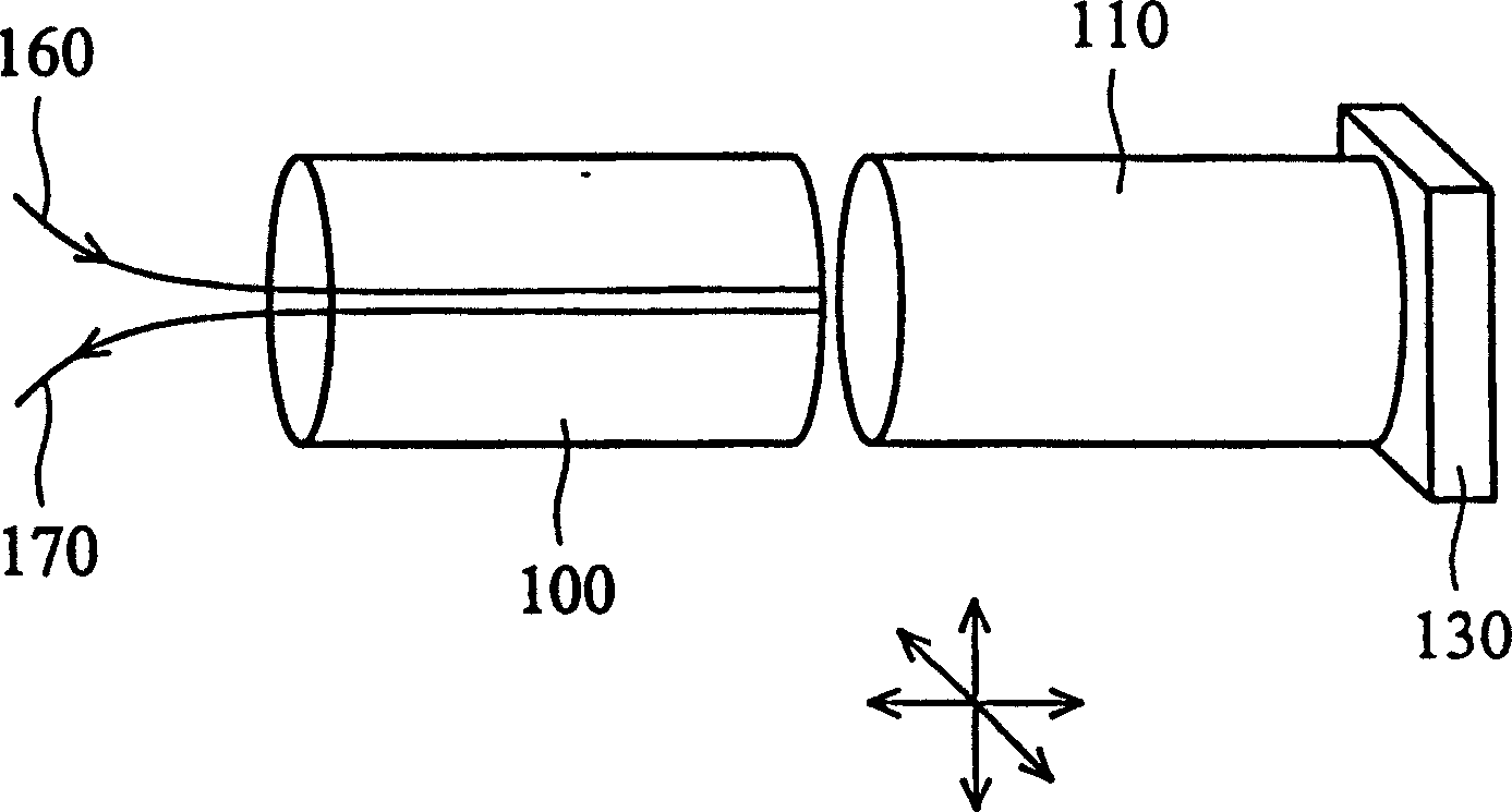
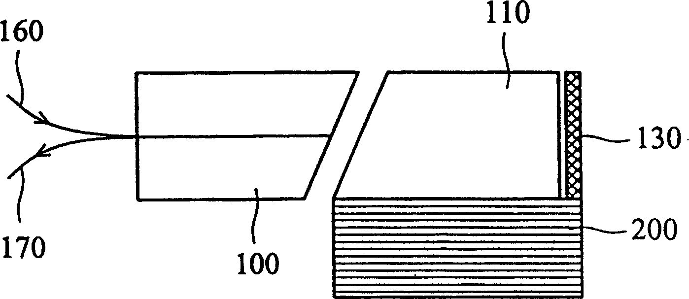
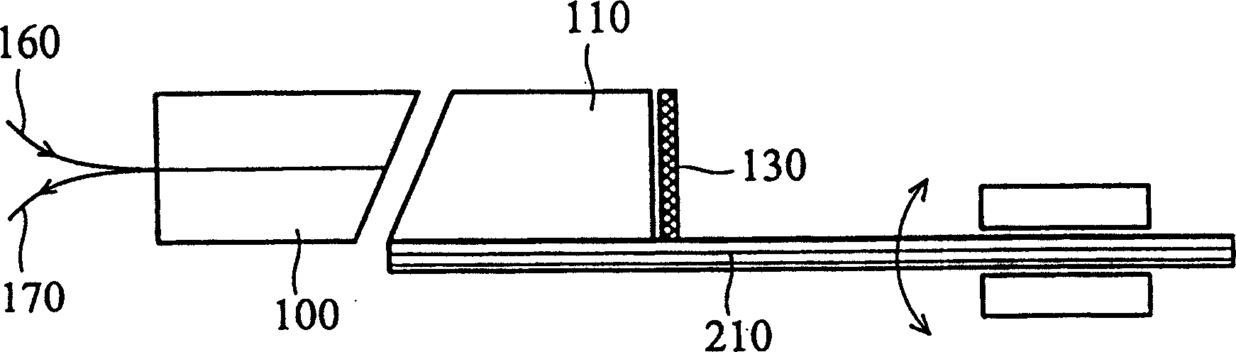
[0015] Such as figure 1 Shown is the structure of the variable optical attenuator of the present invention, the variable optical attenuator of the present invention has a glass ferrule (ferrule) 100, an input optical fiber 160 and an output optical fiber 170, and a gradient index lens (GRIN lens) 110 and a high reflection mirror 130 . in addition, figure 1 Although there is no figure, the variable optical attenuator of the present invention also has a driving device. Each component is described below.

[0016] The glass ferrule 100 has a hole for the input optical fiber 160 and the output optical fiber 170 to be disposed in the hole of the glass ferrule 100 to form a dual fiber pigtail. The gradient index lens 110 and the high reflection mirror 130 are bonded to each other and relatively fixed to form a lens module. More specifically, in the lens module, the high reflection mirror 130 is bonded and fixed to one end of the gradient index lens 110, and the other end of the g...


PUM


Abstract

The light modulating attenuator includes one glass ring with one hole; optical fiber set inside the hole; one lens module with one gradually changed refractive index lens and one high reflectivity reflector jointed to one end of the gradually changed refractive index lens and separated from the glass ring by certain interval; and one driver jointed to the lens module to control the relative motion of the lens module to the glass ring. The driver is one piezoelectric actuator to control the motion of the lens module in piezoelectric mode.

Description

technical field [0001] The invention relates to an adjustable variable optical attenuator, in particular to an adjustable variable optical attenuator which is used in combination with a reflective mirror and a gradient refractive index lens. Background technique [0002] In the optical communication network, the transmission between signals is completed by light. Since the intensity of the optical signal will exceed the detection range of the receiving end, the attenuation of the optical signal is necessary during the transmission process. At this time, the optical attenuator (Optical Attenuator) is usually used to effectively control and change the light intensity to meet the needs of the entire communication system. Modulation optical attenuator (Variable OpticalAttenuator, VOA) technology. [0003] There are many forms of adjustable optical attenuators in the prior art, and a common method is to change the components or relative positions of the adjustable optical attenu...

Claims


Application Information

Patent Timeline
IPC IPC(8): G02B6/32G02F1/19
Inventor 李彦铮程仁宏谢达理
Owner BROWAVE CORP
Why Eureka
Try Eureka