A rotary buckle type electronic chip detection fixture

An electronic chip and detection jig technology, used in electronic circuit testing and other directions, can solve the problems of inability to contact the detection probe, inaccurate detection results, and easy dislocation, etc., to achieve accurate and reliable detection results, long service life, and easy to use. Effect

Active Publication Date: 2016-03-23
东莞光韵达光电科技有限公司
View PDF8 Cites 0 Cited by
  • Summary
  • Abstract
  • Description
  • Claims
  • Application Information

AI Technical Summary

Problems solved by technology

[0003] Electronic chips usually need to be tested in the selection of factory quality inspection, recycled product inspection, and performance testing. Usually, the detection fixture includes a jig bottom plate with a detection circuit, and a detection base is fixed on the jig bottom plate. The detection probe connected to the detection circuit and matched with the electronic chip is set on the bottom plate of the fixture; when testing, the electronic chip is placed on the detection base, and the detection probe is in contact with the detection point of the corresponding electronic chip. A simple pressing block on the upper end presses the chip or sometimes the chip is welded on the detection base so that the chip can be tested against the detection probe. Some parts cannot be in contact with the detection probe, resulting in inaccurate detection results. In addition, the way of welding and fixing is complicated, and it is easy to cause damage to the electronic chip and the detection base

Method used


Image

  • A rotary buckle type electronic chip detection fixture
  • A rotary buckle type electronic chip detection fixture
  • A rotary buckle type electronic chip detection fixture

Examples


Embodiment Construction

[0018] Attached below Figure 1-4 The present invention is further elaborated:

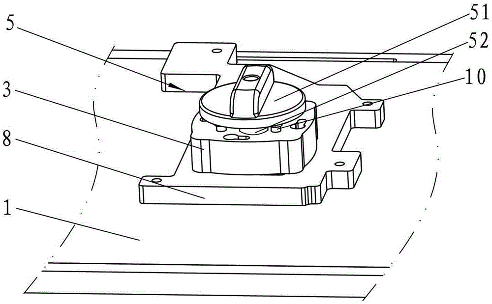
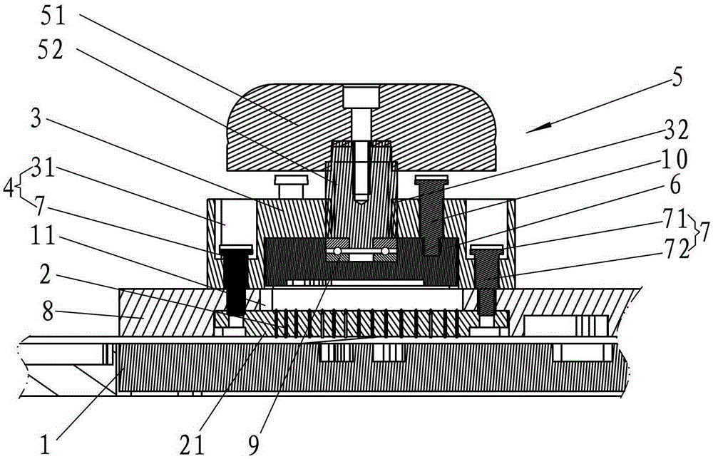
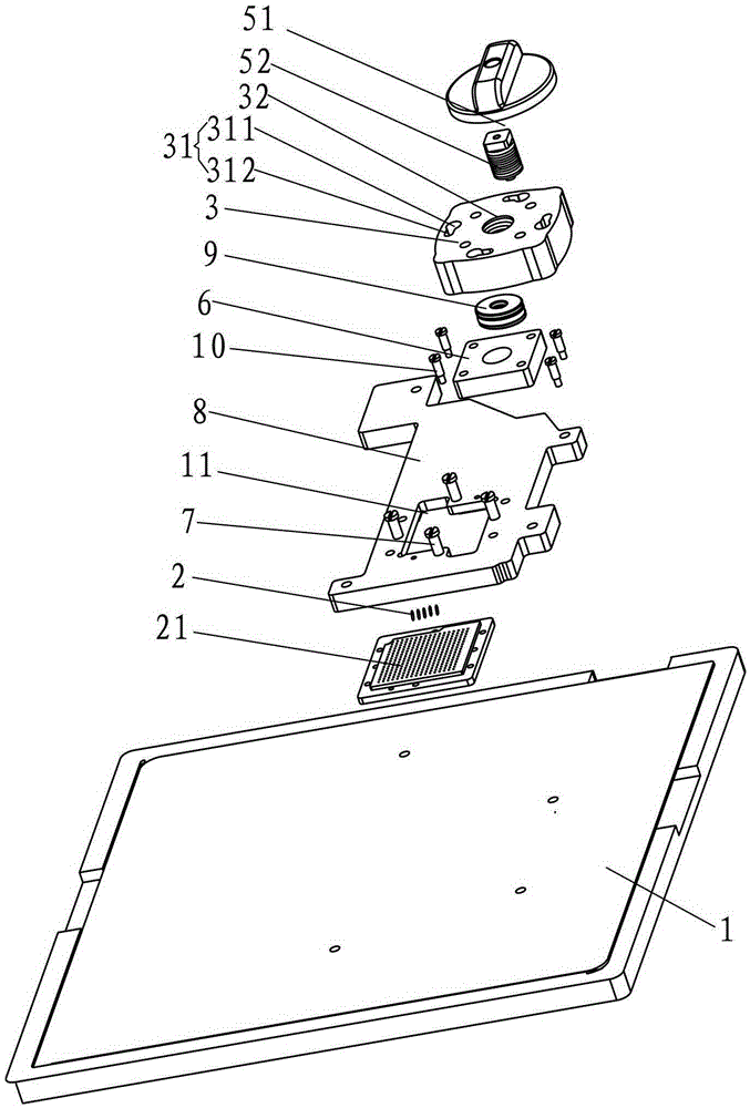
[0019] A rotary buckle type electronic chip detection jig, comprising a jig bottom plate 1 provided with a detection circuit, a chip accommodating cavity 11 for detecting an electronic chip is set on the jig bottom plate 1, and a connection detection circuit is arranged in the chip accommodating cavity 11 and The detection probe 2 matched with the electronic chip is arranged, the screw buckle pressing plate 3 is arranged above the chip accommodating cavity 11, and the twist buckle pressing plate 3 and the jig bottom plate 1 are provided with a twist buckle device 4 that can separate or fix the two. A spinning device 5 is arranged on the board 3, and the bottom end of the spinning device 5 is connected with a chip pressing block 6 pressed against the electronic chip.

[0020] As a preferred embodiment, the turnbuckle device 4 of this embodiment includes two or more spinner columns 7 arranged on th...


PUM


Abstract

The invention relates to the technical field of electronic testing equipment, in particular to a rotating and buckling type electronic chip detection jig. A chip accommodating cavity for testing an electronic chip is disposed on a jig bottom plate. A rotating and buckling pressing plate is disposed on the chip accommodating cavity. A rotating and pressing device is arranged on the rotating and buckling pressing plate. The bottom end of the rotating and pressing device is connected with a chip pressing block for pressing the electronic chip. When the detection jig is in use, the electronic chip is placed in the chip accommodating cavity. The chip accommodating cavity plays a positioning role for the electronic chip so as to avoid malposition. The rotating and buckling pressing plate is disposed on the jig bottom plate through a rotating and buckling device in rotating and buckling mode, and then the rotating and pressing device is rotated so as to enable the chip pressing block to smoothly press towards the electronic chip. Consequently, the upper end of the electronic chip is stressed uniformly, a detected portion of the electronic chip fully contacts with a detection probe, and detection results are accurate and reliable. In addition, the rotating and buckling type electronic chip detection jig has the advantages of being simple in structure, convenient to use and long in service life.

Description

technical field [0001] The invention relates to the technical field of electronic detection equipment, in particular to a spin-type electronic chip detection jig. Background technique [0002] In the 1990s, with the advancement of integration technology, the improvement of equipment and the use of deep submicron technology, LSI, VLSI, and ULSI appeared one after another. The integration of electronic chips continued to increase, and the requirements for integrated circuit packaging became stricter. increases, power consumption also increases. In order to meet the needs of development, on the basis of the original packaging varieties, electronic chips have added a new variety - ball grid array packaging, referred to as BGA (BallGridArrayPackage). At present, various electronic chips are widely used in various industries in the electronic field: computers, mobile phones, Computer north and south bridges, Mp3, MP4, DVD, DVB, printers, communication terminals, industrial contro...

Claims


Application Information

Patent Timeline
Patent Type & Authority Patents(China)
IPC IPC(8): G01R31/28
Inventor 周傲雪姚彩虹
Owner 东莞光韵达光电科技有限公司
Why Eureka
Try Eureka