A flip-type electronic chip detection fixture

An electronic chip and detection jig technology, applied in the direction of electronic circuit testing, etc., can solve the problems of inability to contact the detection probe, inaccurate detection results, and easy dislocation, etc., to achieve accurate and reliable detection results, long service life, and simple operation. Effect

Active Publication Date: 2015-10-28
东莞光韵达光电科技有限公司
View PDF7 Cites 1 Cited by
  • Summary
  • Abstract
  • Description
  • Claims
  • Application Information

AI Technical Summary

Problems solved by technology

[0003] Electronic chips usually need to be tested in the selection of factory quality inspection, recycled product inspection, and performance testing. Usually, the detection fixture includes a jig bottom plate with a detection circuit, and a detection base is fixed on the jig bottom plate. The detection probe connected to the detection circuit and matched with the electronic chip is set on the bottom plate of the fixture; when testing, the electronic chip is placed on the detection base, and the detection probe is in contact with the detection point of the corresponding electronic chip. A simple pressing block on the upper end presses the chip or sometimes the chip is welded on the detection base so that the chip can be tested against the detection probe. Some parts cannot be in contact with the detection probe, resulting in inaccurate detection results. In addition, the way of welding and fixing is complicated, and it is easy to cause damage to the electronic chip and the detection base

Method used


Image

  • A flip-type electronic chip detection fixture
  • A flip-type electronic chip detection fixture
  • A flip-type electronic chip detection fixture

Examples


Embodiment Construction

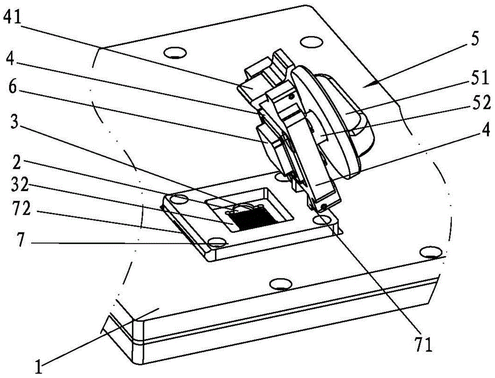
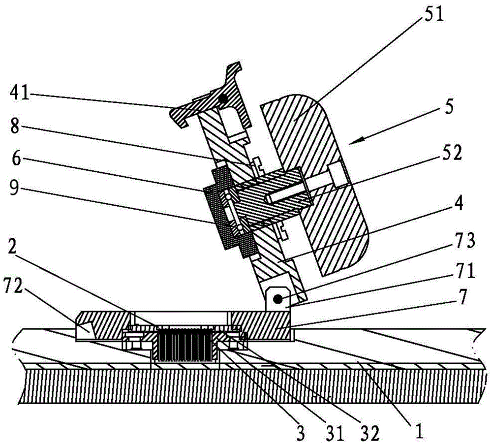
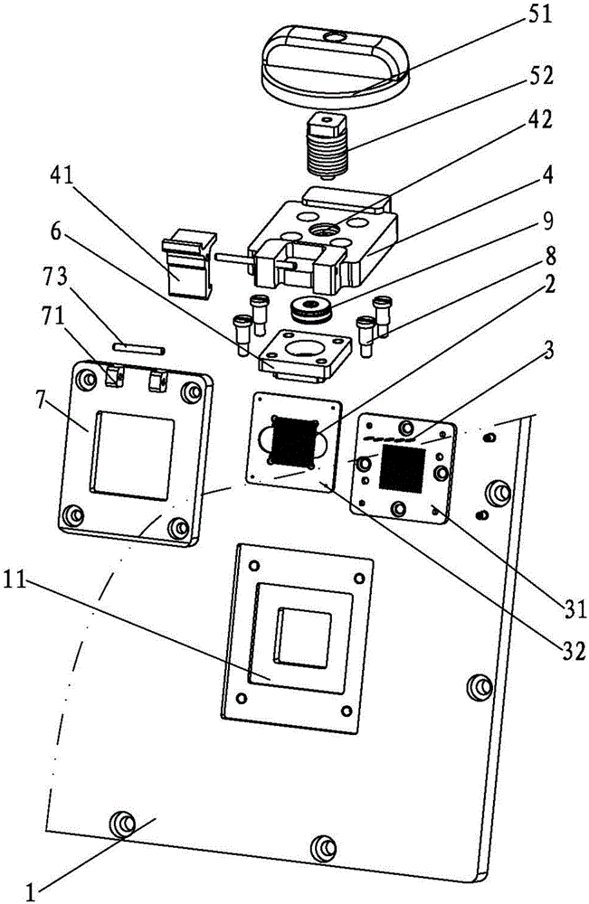
[0016] Attached below Figure 1-3 The present invention is further elaborated:

[0017] A flip-type electronic chip detection jig, comprising a jig bottom plate 1 provided with a detection circuit, a chip accommodating cavity 2 for detecting electronic chips is set on the jig bottom plate 1, and a detection circuit is arranged in the chip accommodating cavity 2 and connected to the chip accommodating cavity 2. The detection probe 3 is matched with the electronic chip, and the cover pressing plate 4 is arranged above the accommodating cavity 2. One side of the cover pressing plate 4 is hinged and arranged on the jig bottom plate 1. The bottom plate 1 is fastened with the pull button 41, and the flip pressing plate 4 is provided with a spinning device 5, and the bottom end of the spinning device 5 is connected with a chip pressing block 6 pressed against the electronic chip.

[0018] In order to better fix the flip cover pressing plate 4, a "back"-shaped fixed mounting seat 7 i...


PUM


Abstract

The invention relates to the technical field of electronic detection equipment and particularly relates to a turnover type electronic chip detection jig. The turnover type electronic chip detection jig is characterized in that a chip containing cavity for detecting an electronic chip is formed in a jig bottom plate and a turnover pressing plate is arranged above the containing cavity; the bottom end of a rotary pressing device on the turnover pressing plate is connected with a chip pressing block pressing to the electronic chip; when the detection jig is used, the electronic chip is placed into the chip containing cavity and the chip containing cavity has the pipe position effect on the electronic chip, so as to not cause a dislocation phenomenon; the turnover pressing plate hinged with the jig bottom plate covers the electronic chip and is buckled on the jig bottom plate through a pulling buckle; and then the rotary pressing device flatly presses the chip pressing block to the electronic chip, the upper end of the electronic chip is uniformly stressed, and an electronic chip detection part is sufficiently contacted with a detection probe, so that the detection result is accurate and reliable. The detection jig disclosed by the invention also has the advantages of simplicity in operation, convenience for use and long service life.

Description

technical field [0001] The invention relates to the technical field of electronic detection equipment, in particular to a flip-type electronic chip detection jig. Background technique [0002] In the 1990s, with the advancement of integration technology, the improvement of equipment and the use of deep submicron technology, LSI, VLSI, and ULSI appeared one after another. The integration of electronic chips continued to increase, and the requirements for integrated circuit packaging became stricter. increases, power consumption also increases. In order to meet the needs of development, on the basis of the original packaging varieties, electronic chips have added a new variety - ball grid array packaging, referred to as BGA (Ball Grid Array Package). At present, various electronic chips are widely used in various industries in the electronic field: computer , mobile phone, computer north-south bridge, Mp3, MP4, DVD, DVB, printer, communication terminal, industrial control mot...

Claims


Application Information

Patent Timeline
Patent Type & Authority Patents(China)
IPC IPC(8): G01R31/28
Inventor 周傲雪姚彩虹
Owner 东莞光韵达光电科技有限公司
Why Eureka
Try Eureka