Improved structure of wiring terminal

An improved structure and terminal technology, applied in the direction of contact parts, clamping/spring connection, etc., can solve problems such as poor contact, loose overall structure, insufficient clamping force, etc., to improve the clamping force of shrapnel and increase the overall structural strength , The effect of stable clamping

Inactive Publication Date: 2012-12-26
DINKLE ENTERPRISE
View PDF6 Cites 5 Cited by
  • Summary
  • Abstract
  • Description
  • Claims
  • Application Information

AI Technical Summary

Problems solved by technology

[0005] like figure 1 As shown, due to the open shape of the body 91 of the traditional connecting terminal, the overall structural strength is relatively insufficient, and the connecting terminal is composed of different parts, so the overall structure is prone to loosening, and it is also eas

Method used


Image

  • Improved structure of wiring terminal
  • Improved structure of wiring terminal
  • Improved structure of wiring terminal

Examples


Example Embodiment

[0018] The specific implementation manners of the present invention will be further described in detail below in conjunction with the accompanying drawings.

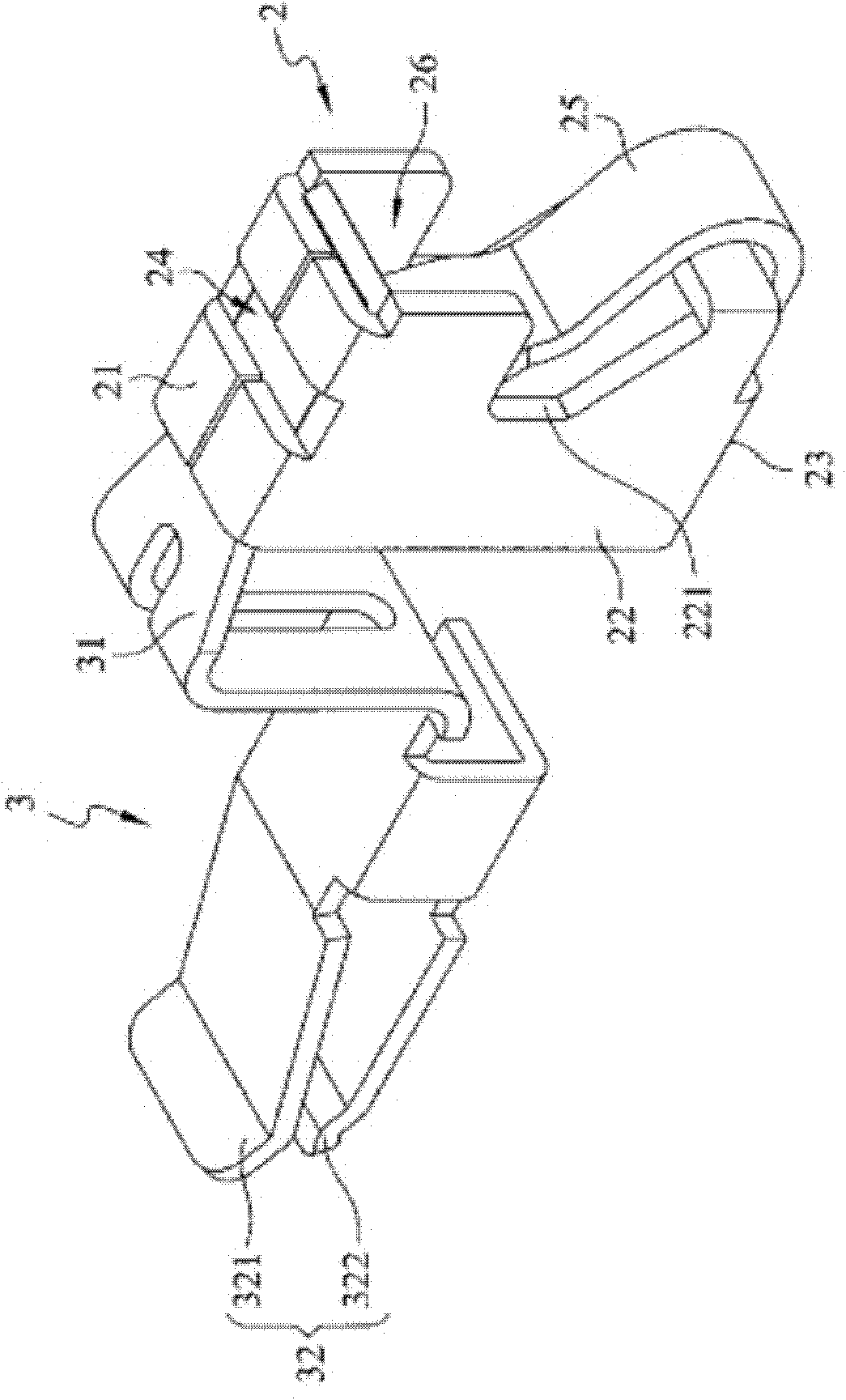
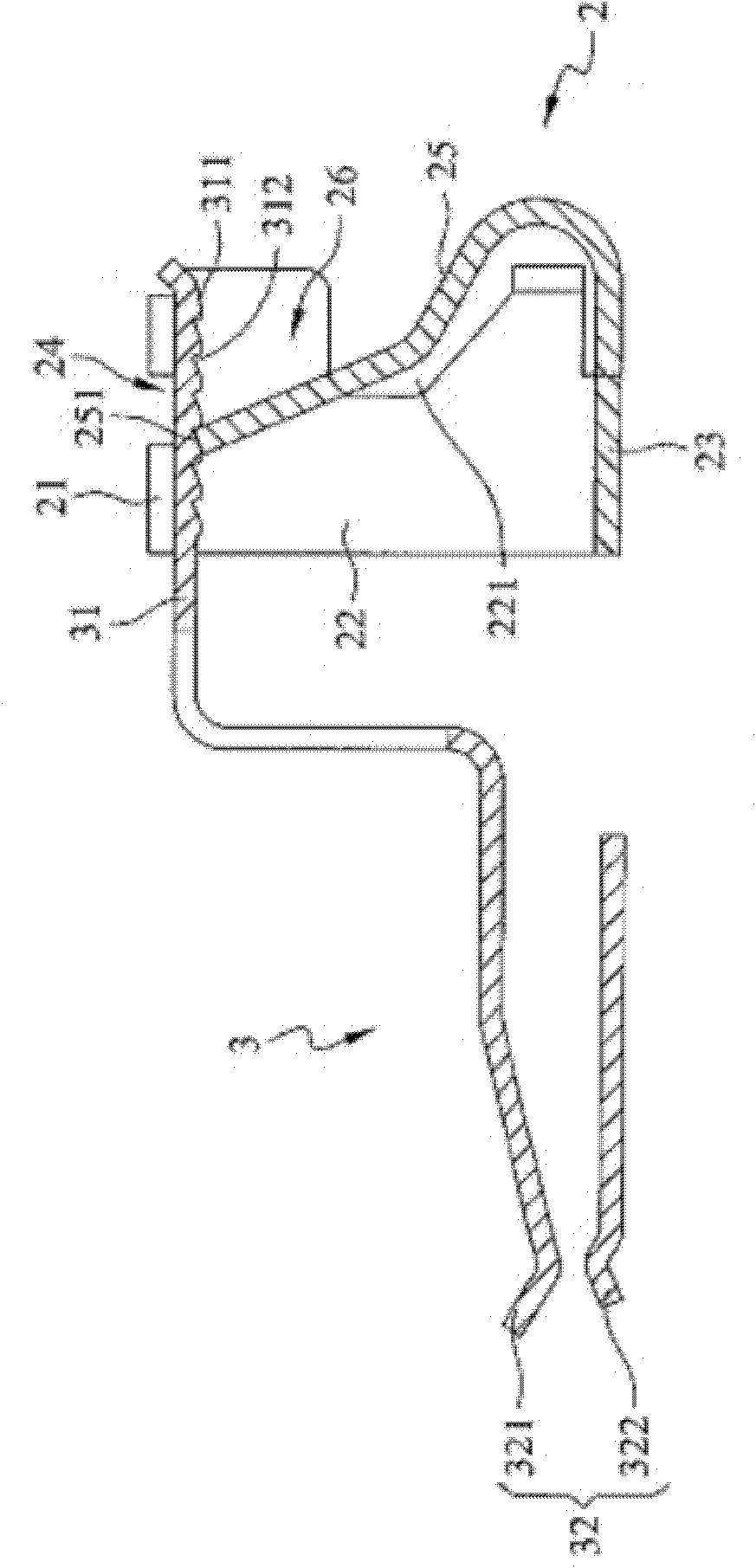
[0019] like figure 2 , image 3 , Figure 4 and Figure 5 As shown, the improved structure of the connection terminal of the present invention includes a box body 2 and a plug connector 3 .

[0020] The box body 2 is an integral molding and includes an upper wall 21, two side walls 22, a lower wall 23, a hole 24 and a shrapnel 25, the upper wall 21, the two side walls 22 and the lower wall 23 are connected to each other and Surrounding a space 26, the hole 24 is opened on the upper wall 21 and communicates with the space 26 and the outside of the box body 2. The elastic piece 25 extends upward from the lower wall 23 to the space 26 and extends with an end 251, and the end 251 protrudes from the upper wall 25. The hole 24 of wall 21 (such as Figure 5 shown).

[0021] In this embodiment, the section of the elastic ...


PUM


Abstract

The invention discloses an improved structure of a wiring terminal. The improved structure comprises a box body and a plug connector, wherein the box body is of an integrally formed member which comprises an upper wall, two side walls, a lower wall, a hole and an elastic sheet; the upper wall, the two side walls and the lower wall surround to form a space; the hole is arranged on the upper wall and communicates the space and the outer part of the box body; the elastic sheet stretches upwards from the lower wall to the space, and stretches to form a tail end; the tail end is protruded and stretches into the hole; the plug connector comprises a plug part and a clamp part; the clamp part comprises an upper clamp elastic sheet and a lower clamp elastic sheet which correspond to each other; the plug part penetrates into the space and is plugged in the box body; the tail end of the elastic sheet pushes against the plug part; and the plug part presses the tail end of the elastic sheet down into the space. With the adoption of the design, the improved structure of the wiring terminal has the effects that the strength of the whole structure is improved, and the clamp force of the elastic sheet is increased, so when the elastic sheet is clamping a transmission line, the transmission line can be stably clamped.

Description

technical field [0001] The invention relates to a connection terminal, in particular to an improved structure of the connection terminal. Background technique [0002] In general electronic products, it is often necessary to perform wiring operations of transmission lines between different electronic components, so as to allow electrical connection and signal transmission between different electronic components. [0003] In order to achieve the above wiring purposes, so-called terminal blocks are generally used. like figure 1 As shown, the perspective view of the conventional terminal block, the terminal block includes a body 91 , an elastic piece 92 and a clamping portion 93 . [0004] Wherein, the body 91 is open and forms a space 911. The clamping portion 93 extends from the body 91 and includes an upper clamping elastic piece 931 and a lower clamping elastic piece 932. welding method) assembled in the space 911 of the body 91. [0005] like figure 1 As shown, due to...

Claims


Application Information

Patent Timeline
IPC IPC(8): H01R13/02H01R4/48
Inventor 吴上财
Owner DINKLE ENTERPRISE
Why Eureka
Try Eureka