

Supporting equipment for bridge engineering construction
A technology for supporting equipment and bridge engineering, used in bridge construction, bridges, erection/assembly of bridges, etc., can solve the problems of anti-aging, poor elasticity, and inconvenient installation of shock-absorbing materials, and achieve high overall structural strength. The effect of long life and easy installation
- Summary
- Abstract
- Description
- Claims
- Application Information
AI Technical Summary
Problems solved by technology
Method used
Image

Examples
Embodiment 1
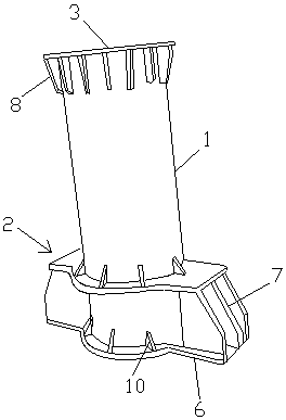
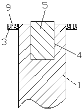
[0022] Such as figure 1 and figure 2 Shown, a kind of support equipment for bridge engineering construction, comprises cylinder 1, base 2 and retaining ring 3, described cylinder 1 is welded on the base 2, and described retaining ring 3 is welded on the top of cylinder 1, so A groove 4 is provided above the middle part of the column body 1, and a shock-absorbing column 5 is arranged in the groove 4. The base 2 includes two bottom plates 6 arranged in parallel, and the inner side of the middle part of the bottom plate 6 is circular. Holes are set, and the middle part of the bottom plate 6 is arranged as an arc-shaped protrusion on the outer side of the middle part. A plurality of partitions 7 are welded between the bottom plate 6, and the bottom of the retaining ring 3 and the outer side of the cylinder 1 are welded in an annular array. A reinforcing rib 8 .
[0023] The surface of the retaining ring 3 is provided with through holes 9 in an annular array.
[0024] The top o...
Embodiment 2
[0034] Such as figure 1 and figure 2 Shown, a kind of support equipment for bridge engineering construction, comprises cylinder 1, base 2 and retaining ring 3, described cylinder 1 is welded on the base 2, and described retaining ring 3 is welded on the top of cylinder 1, so A groove 4 is provided above the middle part of the column body 1, and a shock-absorbing column 5 is arranged in the groove 4. The base 2 includes two bottom plates 6 arranged in parallel, and the inner side of the middle part of the bottom plate 6 is circular. Holes are set, and the middle part of the bottom plate 6 is arranged as an arc-shaped protrusion on the outer side of the middle part. A plurality of partitions 7 are welded between the bottom plate 6, and the bottom of the retaining ring 3 and the outer side of the cylinder 1 are welded in an annular array. A reinforcing rib 8 .
[0035] The surface of the retaining ring 3 is provided with through holes 9 in an annular array.
[0036] The top o...
Embodiment 3
[0046] Such as figure 1 and figure 2 Shown, a kind of support equipment for bridge engineering construction, comprises cylinder 1, base 2 and retaining ring 3, described cylinder 1 is welded on the base 2, and described retaining ring 3 is welded on the top of cylinder 1, so A groove 4 is provided above the middle part of the column body 1, and a shock-absorbing column 5 is arranged in the groove 4. The base 2 includes two bottom plates 6 arranged in parallel, and the inner side of the middle part of the bottom plate 6 is circular. Holes are set, and the middle part of the bottom plate 6 is arranged as an arc-shaped protrusion on the outer side of the middle part. A plurality of partitions 7 are welded between the bottom plate 6, and the bottom of the retaining ring 3 and the outer side of the cylinder 1 are welded in an annular array. A reinforcing rib 8 .
[0047] The surface of the retaining ring 3 is provided with through holes 9 in an annular array.
[0048] The top o...
PUM
 Abstract
Description
Claims
Application Information