Magnetic material powder forming mold

A technology of magnetic materials and forming molds, which is applied in the direction of material forming presses, manufacturing tools, presses, etc., can solve problems such as inconsistent orientation of blanks, uneven magnetic field distribution, and affecting performance, and achieve a wide range of applications.

Active Publication Date: 2013-01-02
JIANGXI JLMAG RARE EARTH
View PDF5 Cites 11 Cited by
  • Summary
  • Abstract
  • Description
  • Claims
  • Application Information

AI Technical Summary

Problems solved by technology

[0007] In addition, due to the uneven distribution of the magnetic field, the orientation direc

Method used


Image

  • Magnetic material powder forming mold
  • Magnetic material powder forming mold
  • Magnetic material powder forming mold

Examples


Embodiment 1

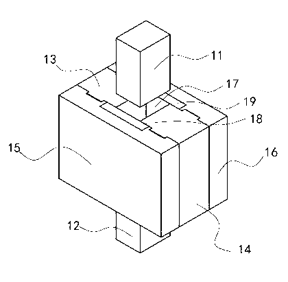
[0034] Such as figure 2 As shown, in this preferred embodiment, the female mold includes four side plates as an example. Described molding die comprises upper ram 11, lower ram 12 and die, and described die includes front side plate 13, rear side plate 14, left side plate 15 and right side plate 16, and described front side plate 13. The rear side plate 14 , the left side plate 15 and the right side plate 16 surround and form a female cavity 17 . Preferably, the inside of the cavity 17 of the female mold is entirely made of a material whose saturation polarization is consistent with that of the magnetic material powder to be pressed; The polarization intensity is consistent with the saturation polarization intensity of the magnetic material powder that needs to be pressed; or the saturation polarization of the material of the front side plate 13, the rear side plate 14, the left side plate 15 and the right side plate 16 The intensity is consistent with the saturation polari...

Embodiment 2

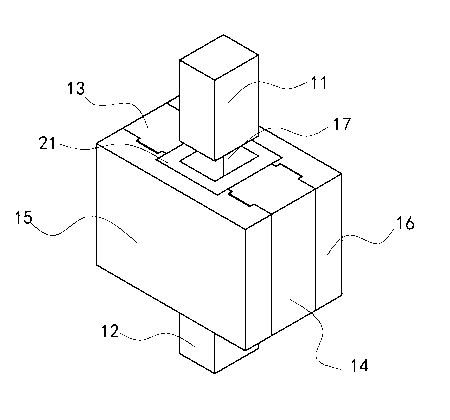
[0042] Such as image 3 As shown, the front side plate 13 and the rear side plate 14 of the female mold cavity 17 are all provided with the isolation plate, and the four isolation plates are connected in sequence to form a hollow cylindrical body 21, the cylindrical body 21 The outer wall cooperates with the inner wall of the cavity 17 of the female mold, and the shape of the cavity of the cylindrical body 21 matches the shape of the blank to be pressed. Four isolation plates form the cylindrical body 21 as an integral structure, which is easy to install. Correspondingly, in order to cooperate with the cylindrical body 21 , the lengths of the front side plate 13 and the rear side plate 14 need to be shortened accordingly.

Embodiment 3

[0044] Such as Figure 4 As shown, when it is necessary to compress the special-shaped magnetic material powder, the shape of the inner cavity of the cylindrical body 21 can also be changed according to the required shape, Figure 4 The blank oriented obliquely at an angle of 45° as shown in , has an inner cavity similar in shape to the blank in the middle of the cylindrical body 21 .


PUM


Abstract

The invention discloses a magnetic material powder forming mold, which comprises a female die, wherein a female die cavity is arranged in the female die; and the saturation polarization strength of at least one side face of the female die cavity is consistent with the saturation polarization strength of magnetic material powder to be pressed. According to the magnetic material powder forming mold, the saturation polarization strength of the at least one side face of the female die cavity is consistent with the saturation polarization strength of the magnetic material powder, so that an edge distortion phenomenon of a magnetic field is transferred from the magnetic material powder to a side face of the female die cavity made of the material, the magnetic field of the magnetic material powder is guaranteed to be a uniform magnetic field, and the performance of a blank made through the mold is guaranteed. Because of an arrangement mode of an isolating plate, the material with the saturation polarization strength consistent with that of the magnetic material powder is arranged on different side faces according to different requirements, so that the application range is wide and the pressing of the magnetic powder is not affected.

Description

technical field [0001] The invention relates to the field of mold manufacturing, in particular to a magnetic material powder forming mold. Background technique [0002] Such as figure 1 As shown, the mold currently used is composed of a female mold, an upper indenter 5, and a lower indenter 6. The female mold is composed of four side plates, front, rear, left, and right. Among them, the left side plate 3 and the right side plate 4 use magnetic materials. It is Gr12 steel or GGr15 steel; the front side plate 1 and the rear side plate 2 are non-magnetic materials, generally 304 stainless steel, non-magnetic die steel, non-magnetic hard alloy, etc. The upper indenter 5 and the lower indenter 6 are also Non-magnetic material. [0003] The magnetic powder needs to have a magnetic field orientation during the pressing process, so that the magnetization direction of the powder is the same as the direction of the applied magnetic field. The coil for orientation is installed on th...

Claims


Application Information

Patent Timeline
IPC IPC(8): B22F3/03B30B11/02B30B15/02
Inventor 蔡报贵周铁夫金小平胡勇毛华云岳崇斌
Owner JIANGXI JLMAG RARE EARTH
Why Eureka
Try Eureka