
Lock flight system with functions of navigation, power generation and flood discharge

A ship lock system and functional technology, applied in ship locks, hydroelectric power generation, hydroelectric power stations, etc., can solve problems such as power generation and flood discharge multi-level ship lock solutions that have not yet been seen

Inactive Publication Date: 2013-01-02
HOHAI UNIV
View PDF3 Cites 11 Cited by
  • Summary
  • Abstract
  • Description
  • Claims
  • Application Information

AI Technical Summary

Benefits of technology

This technology helps use more energy from waves without causing damage or losing equipment during times that there may be no navigational needs for boats. It also allows boat owners to operate their locks while they're undergoing droughts due to lacking hydraulic oil pressure.

Problems solved by technology

The technical problem addressed by this patented technology relates to efficiently converting excessive amounts of water from one form (the upper stream) to another type for use during navigation or other operations without losing any useful work done due to lack of sufficient energy stored within the lower portion of the locked vessel's hydraulics system.

Method used


Image

  • Lock flight system with functions of navigation, power generation and flood discharge

Examples


Embodiment Construction

[0011] Below in conjunction with accompanying drawing and specific embodiment the present invention is described in further detail:

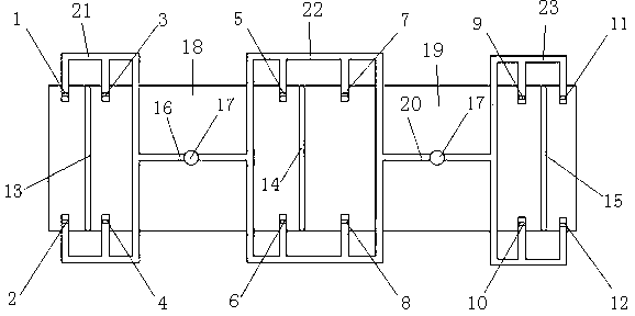
[0012] Such as figure 1 As shown, the present invention includes an upstream gate 13, a midstream gate 14 and a downstream gate 15, forming an upstream lock chamber 18 and a downstream lock chamber 19 between them. A straight section 16 of the upstream water delivery corridor is provided between the upstream gate 13 and the midstream gate 14, a straight section 20 of the downstream water delivery corridor is provided between the midstream gate 14 and the downstream gate 15, and a straight section 16 of the upstream water delivery corridor Water turbines 17 are installed in the straight section 20 of the downstream water delivery corridor.

[0013] One end of the straight section 16 of the upstream water delivery corridor is connected to the upstream water delivery profile 21 , the other end is connected to one end of the midstream water deliver...


PUM


Abstract

The invention discloses a lock flight system with the functions of navigation, power generation and flood discharge. The lock flight system is characterized by comprising an upper gate, a middle gate and a lower gate, an upper lock chamber and a lower lock chamber are formed between the upper gate, the middle gate and the lower gate, an upper water delivery gallery straight segment is arranged between the upper gate and the middle gate, and a lower water delivery gallery straight segment is arranged between the middle gate and the lower gate; one end of the upper water delivery gallery straight segment is connected with an upper water delivery gallery and the other end is connected with one end of a middle water delivery gallery, and the other end of the middle water delivery gallery is connected with one end of the lower water delivery gallery; the upper water delivery gallery is provided with a water inlet and a water outlet at two sides of the upper gate respectively, the middle water delivery gallery is provided with a water inlet and a water outlet at two sides of the middle gate, and the lower water delivery gallery is provided with a water inlet and a water outlet at two sides of the lower gate; a water turbine is arranged in each of the upper water delivery gallery straight segment and the lower water delivery gallery straight segment. By matching with different valve opening and closing schemes, the lock flight system realizes the function of generating power in non-flood seasons and flood seasons.

Description


Claims


Application Information

Patent Timeline
Owner HOHAI UNIV
Learn More