
Ray back scattering imaging system for discriminating depth information

An imaging system, backscattering technology, used in material analysis, measuring devices, instruments, etc. using wave/particle radiation, which can solve problems such as the inability to judge the depth of the object to be measured.

Active Publication Date: 2013-01-02
INST OF HIGH ENERGY PHYSICS CHINESE ACADEMY OF SCI
View PDF5 Cites 19 Cited by
  • Summary
  • Abstract
  • Description
  • Claims
  • Application Information

AI Technical Summary

Problems solved by technology

[0005] The purpose of the present invention is to provide a ray backscatter imaging system that can discriminate depth information, so as to solve the problem that the existing backscatter imaging cannot judge the depth of the measured object

Method used


Image

  • Ray back scattering imaging system for discriminating depth information
  • Ray back scattering imaging system for discriminating depth information
  • Ray back scattering imaging system for discriminating depth information

Examples


Embodiment Construction

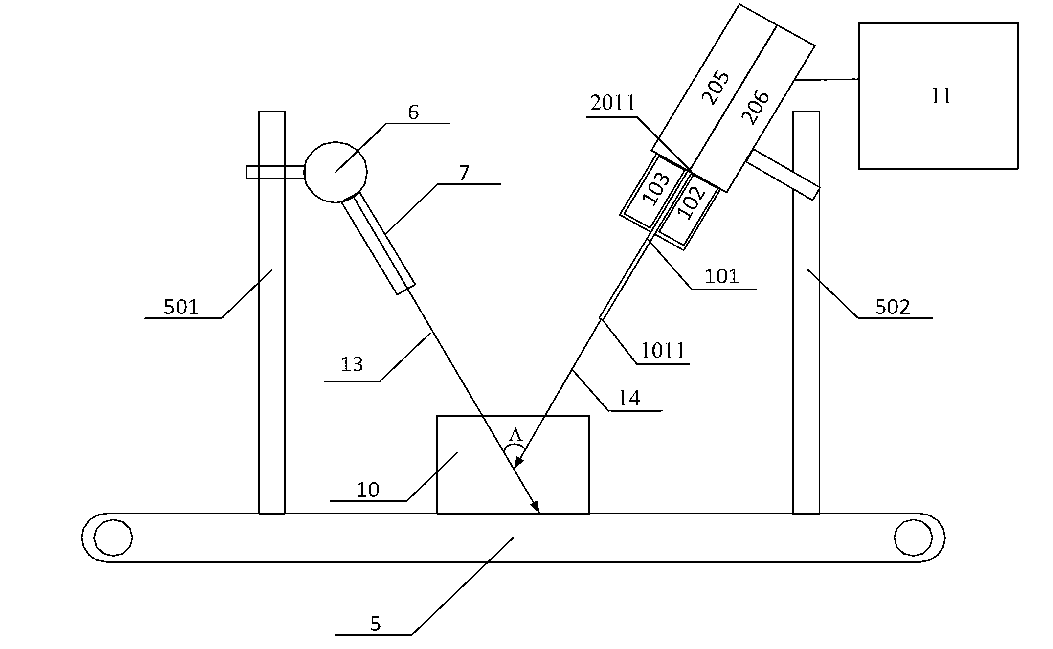
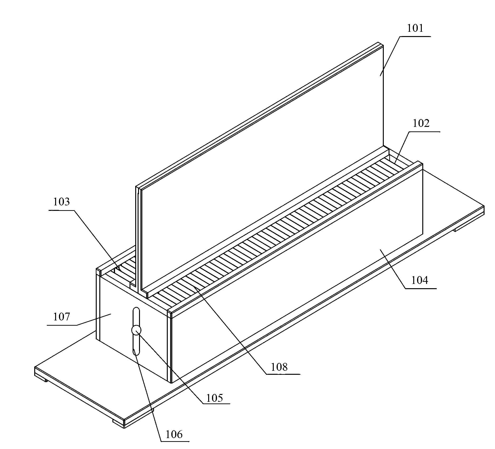
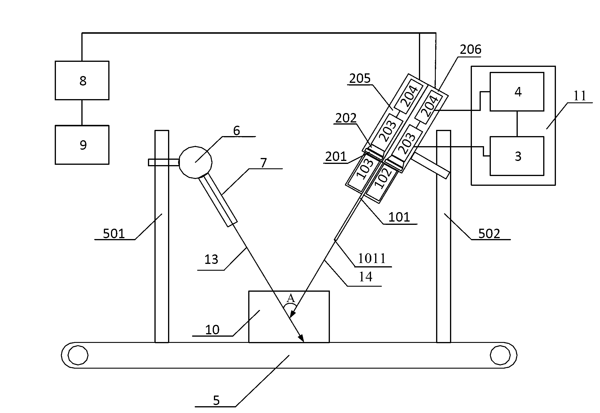
[0023] figure 1 Shown is a schematic structural view of an embodiment of the ray backscatter imaging system of the present invention, as figure 1 As shown, the ray backscatter imaging system includes: a mobile device 5, a first bracket 501, a second bracket 502, a radiation source 6, a first collimator 7, a detector 205 and a detector 206, and a second collimator 102 and a second collimator 103 , a light blocking plate 101 and a power supply device 11 .

[0024] Such as figure 1 As shown, the specific structure of the ray backscatter imaging system is as follows. The moving device 5 in this embodiment is a transmission belt 5 . The first bracket 501 and the second bracket 502 are respectively arranged front and back along the driving direction of the transmission belt 5 . The radiation source 6 is fixed on the first bracket 501 . The first collimator 7 is matched and fixed with the radiation source 6 . The emission side of the first collimator 7 is obliquely downward tow...


PUM


Abstract

The invention discloses a ray back scattering imaging system for discriminating depth information. The system comprises a ray source, a first collimating device, a plurality of groups of detectors, a plurality of second collimating devices and at least one light barrier. The relative positions of the ray source and the groups of detectors are adjusted, restriction of second collimating devices and the light barrier is adjusted, detection geometrical angles of the groups of detectors are different, strength differences of back scattering rays collected by detection units at responding positions of different groups of detectors are compared, and the depth information that rays are subjected to Compton scattering effect in an object to be detected is determined. Strength differences of back scattering rays collected by detection units at different positions of the same group of detectors are compared, and transverse information that rays are subjected to Compton scattering effect in the object to be detected is obtained. Through the relative motion formed by an integral body which is formed by the ray source and the groups of detectors and the object to be detected, the continuous sweeping is conducted, and integral multi-layer back scattering images are obtained.

Description

technical field [0001] The invention relates to the technical field of image detection, in particular to a ray backscatter imaging system capable of discriminating depth information. Background technique [0002] X-ray backscatter imaging technology (hereinafter referred to as backscatter imaging) is a new type of non-invasive imaging technology based on Compton scattering, which has been used in industrial flaw detection, hidden object search, border security inspection and other fields. Backscatter imaging has three advantages over other imaging techniques. (1) The location of the ray source and the detector is flexible, especially it can be placed on the same side of the measured object at the same time, so backscatter imaging is suitable for detecting large objects that are difficult to penetrate by traditional X-ray transmission technology and hidden inside walls or subterranean objects. (2) Backscatter imaging is particularly sensitive to elements with low atomic num...

Claims


Application Information

Patent Timeline
IPC IPC(8): G01N23/203
Inventor 魏龙刘彦韬马创新章志明李道武魏存峰朱美玲帅磊胡婷婷丰宝桐黄先超柴培唐浩辉李婷王英杰张译文庄凯王晓明姜小盼
Owner INST OF HIGH ENERGY PHYSICS CHINESE ACADEMY OF SCI
Learn More