Piezoelectric motor

A piezoelectric motor, piezoelectric body technology, applied in piezoelectric effect/electrostrictive or magnetostrictive motors, generators/motors, electrical components, etc. and other problems, to achieve the effect of improving service life, ensuring stability, and high compressive stiffness.

Inactive Publication Date: 2015-06-03
NANJING UNIV OF AERONAUTICS & ASTRONAUTICS
View PDF5 Cites 0 Cited by
  • Summary
  • Abstract
  • Description
  • Claims
  • Application Information

AI Technical Summary

Problems solved by technology

[0012] First, the key to the stepping of the inchworm-type clamping piezoelectric motor is that the two clamping units can alternately lock the parallel guide rails, and the two clamping units are separated by a certain distance in the direction of motion, which requires parallel guide rails The parallelism must be high enough. Under the existing technical conditions, it is very difficult to realize the high parallelism of the two guide rails with a long distance, which requires high production cost;
[0013] Second, the parallel guide rails of the inchworm-type clamping stepping piezoelectric motor are fixed, and the wear at both ends of the clamping unit will eventually lead to the inability to achieve clamping, resulting in failure;
[0014] Third, the laminated piezoelectric stack can only withstand a small pulling force, but can withstand a large thrust. Therefore, when the drive unit is shortened, the working capacity of the laminated piezoelectric stack is very small, which reduces the movement of the mover. s efficiency;
[0015] Fourth, when all the laminated piezoelectric stacks are powered off, the locking force between the clamping unit and the parallel guide rails is much smaller than that of the clamping unit locking the parallel guide rails, so the inchworm-type clamping step Piezoelectric motors have almost no power-off self-locking ability

Method used


Image

  • Piezoelectric motor
  • Piezoelectric motor
  • Piezoelectric motor

Examples


Embodiment Construction

[0042] The accompanying drawings disclose, without limitation, the structural schematic diagrams of the preferred embodiments involved in the present invention; the technical solution of the present invention will be described in detail below in conjunction with the accompanying drawings.

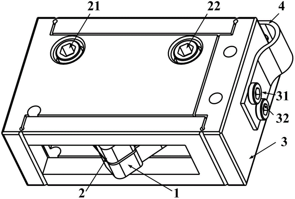
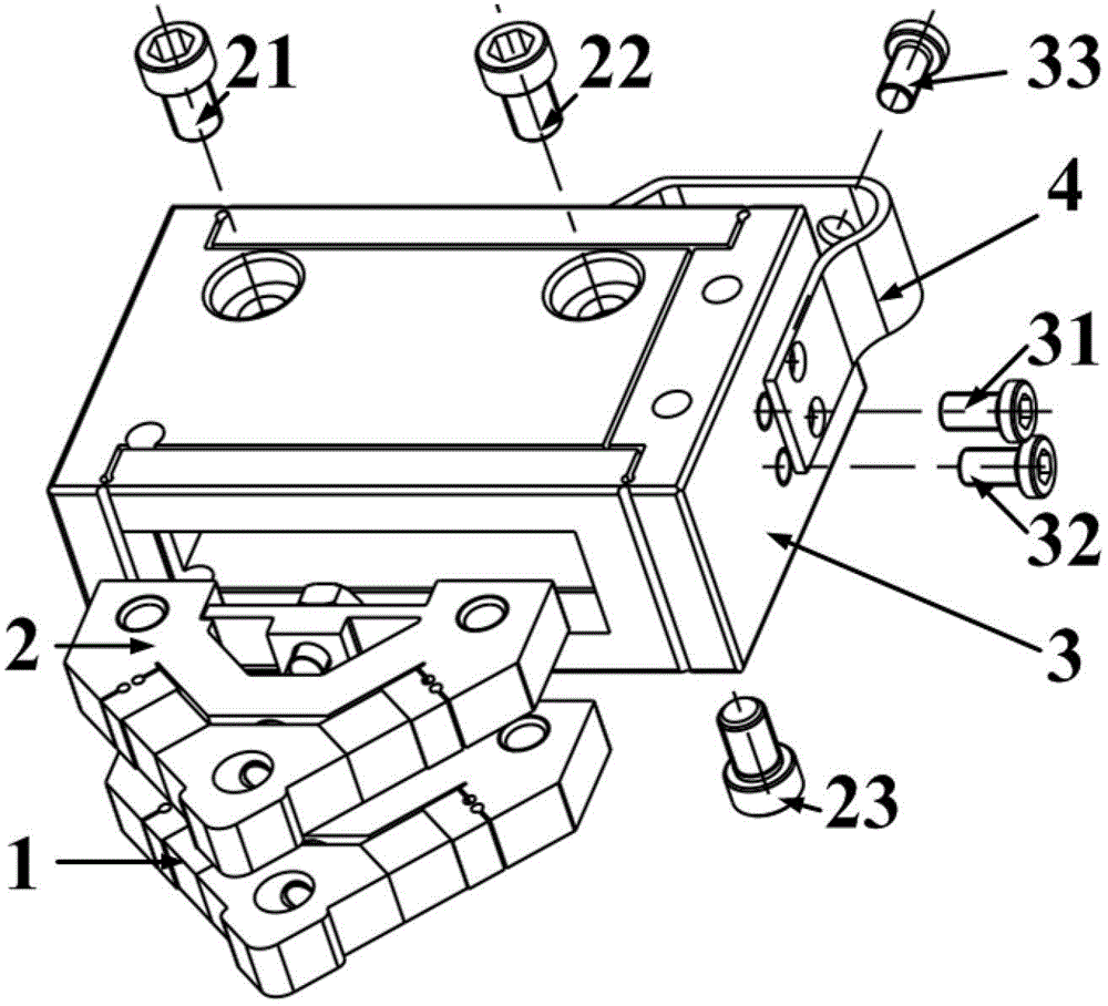
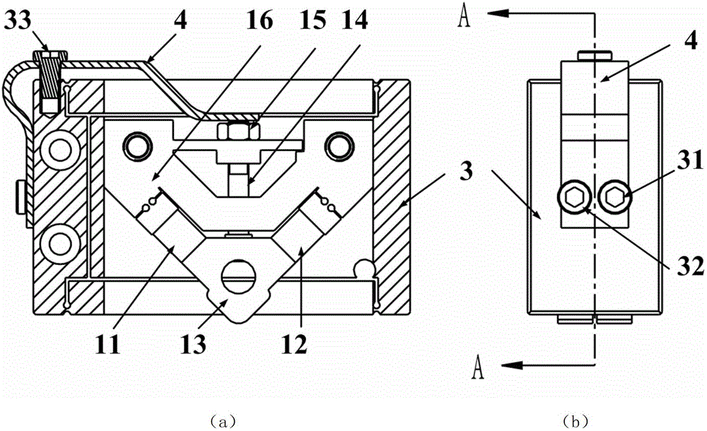
[0043] Such as Figure 5 , Figure 6 As shown, the piezoelectric motor of the present invention includes a piezoelectric body, an elastic connector and a moving part. The piezoelectric body is in elastic contact with the moving part through the elastic deformation of the elastic connector, that is, the driving foot of the piezoelectric body is connected through the elastic The elastic force provided by the piece is always pressed against the moving piece, and the moving piece can be Figure 5 For the shown mover, the piezoelectric motor of the present invention is a linear piezoelectric motor at this time; it can also be Figure 6 As shown in the rotor, the piezoelectric motor of the pres...


PUM


Abstract

The invention discloses a piezoelectric motor. The piezoelectric motor comprises a piezoelectric body, a moving part and an elastic connecting part, wherein the piezoelectric body contacts with the moving part elastically through elastic deformation of the elastic connecting part, the piezoelectric body comprises a guide box and a piezoelectric actuating unit which is arranged inside the guide box, the guide box comprises a guide box body and an actuating unit installation face, the actuating unit installation face is arranged on the guide box body and is connected with the guide box body in a flexible mode, the piezoelectric actuating unit is in an axial symmetric structure and comprises a base body, a driving foot and two groups of laminated piezoelectric stacks, the two groups of laminated piezoelectric stacks are arranged between the base body and the driving foot in a pressing mode, the base body is fixedly connected with the actuating unit installation face, the driving foot extends out of an inner cavity of the guide box and then contacts with the moving part, one end of the elastic connecting part is fixed with the guide box body, the other end of the elastic connecting part contacts with an end portion of the base body, which is opposite to the driving foot, and each of the two groups of laminated piezoelectric stacks is connected with a corresponding excitation power supply. Thus, the piezoelectric motor has the advantages of being large in thrust, low in manufacturing cost, long in life and high in efficiency, and simultaneously, the piezoelectric motor has a power-down self-locking function.

Description

technical field [0001] The invention relates to a piezoelectric motor and belongs to the technical field of piezoelectric precision actuation. Background technique [0002] With the development of micro / nano technology, research in many engineering technology fields urgently needs submicron and micro / nano precision actuators. It is difficult to break through in the direction. With the development of material science, new functional materials have proposed new solutions for these applications. Among them, the discovery of the inverse piezoelectric effect and the emergence of piezoelectric ceramic (PZT) materials with superior performance have made piezoelectric precision actuators The research has received extensive attention and has shown broad application prospects in the field of precision motion. [0003] One of the outstanding advantages of piezoelectric ceramics as actuators is their high stiffness, high load capacity and wide frequency response, but the output strain...

Claims


Application Information

Patent Timeline
Patent Type & Authority Patents(China)
IPC IPC(8): H02N2/00H02N2/02H02N2/10H02N2/04H02N2/12
Inventor 黄卫清王寅
Owner NANJING UNIV OF AERONAUTICS & ASTRONAUTICS
Why Eureka
Try Eureka