Telescoping operating arm, operating device and injection moulding device

A manipulation device and injection molding technology, applied in the direction of claw arms, manipulators, manufacturing tools, etc., can solve the problems of contact, short extension length, etc.

Active Publication Date: 2013-01-09
ENGEL AUSTRIA
View PDF5 Cites 5 Cited by
  • Summary
  • Abstract
  • Description
  • Claims
  • Application Information

AI Technical Summary

Problems solved by technology

[0009] but if Figure 4 As shown in , in the stretched state A there is the following problem: The stretched length Z is rather short, because the guide blocks 5 and 6 will touch each other when moving further along the stretched direction F

Method used


Image

  • Telescoping operating arm, operating device and injection moulding device
  • Telescoping operating arm, operating device and injection moulding device
  • Telescoping operating arm, operating device and injection moulding device

Examples


Embodiment Construction

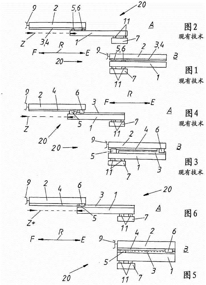
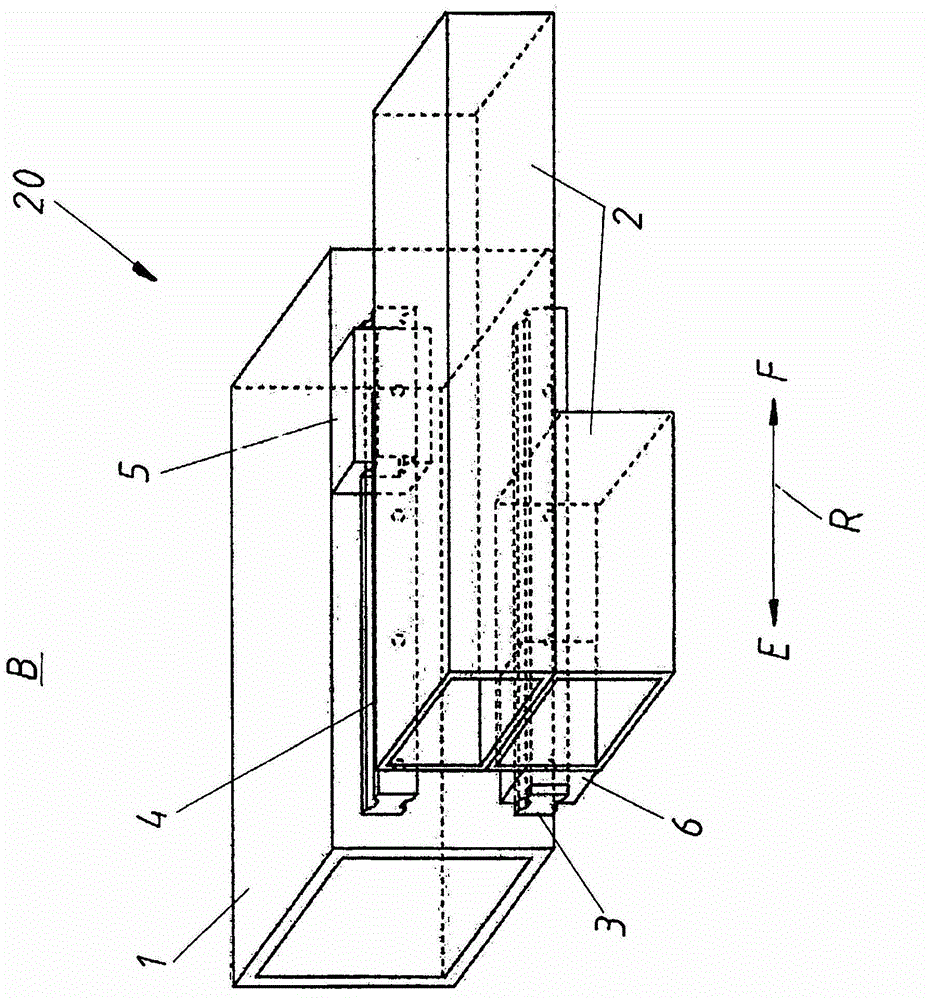
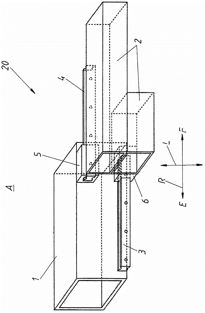
[0024] as already described Figures 1 to 4 On the one hand, the shortcomings existing in the prior art can be Figure 5 Shown to be overcome, the way is: in the shown retracted state B, the second guide block 6 that is arranged at the end of the second branch arm 2 pointing to the retraction direction E and shown in the previous part and The first guide rail 3 , likewise shown in the previous section, corresponds (ie matches) on the first partial arm 1 . In contrast, the guide block 5 arranged at the end of the first partial arm 1 pointing in the direction of extension F is shown in dashed lines in the rear part and is connected to the same in the rear part (in dashed lines) The second guide rail 4 of the second branch arm 2 is corresponding. Thus, especially compared to the figure 1 and 2 With the known prior art shown in , significantly better stability is obtained even in retracted state B.

[0025] exist Figure 6 A further advantage can be seen in , whereby a longe...


PUM


Abstract

The present invention relates to a telescoping operating arm, an operating device and an injection moulding device, wherein the operating arm (20) of the operating device (10) used for the injection moulding device comprises a first branch arm (1) and a second branch arm (2), the first and second branch arms and at least two guide blocks traveling on at least two guide rails (3, 4) can move through the at least two guide rails (3, 4), the guide block (5) arranged on the first branch arm (1) can travel on the guide rail (4) arranged on the second branch arm (2), the guide block (6) arranged on the second branch arm (2) can travel on the guide rail arranged on the first branch arm (1), and the guide block (5) arranged on the first branch arm (1) partially and preferably covers the guide block (6) arranged on the second branch arm (2) in a vision line (L) vertical to the orientation of the guide rails (3, 4), under the stretching state of the branch arms (1, 2).

Description

technical field [0001] The invention relates to a manipulating arm for a manipulating device of injection molding equipment, which comprises a first branch arm and a second branch arm, and the first branch arm and the second branch arm can pass through at least two mutually parallel guide rails and At least two guide blocks that can travel on the guide rails move, wherein the guide blocks arranged on the first branch arm can travel on the guide rails arranged on the second branch arm, and the guide blocks arranged on the second branch arm can travel on the guide rails arranged on the second branch arm. The block can travel on the guide rail provided on the first branch arm. The invention also relates to a manipulating device equipped with such a manipulating arm, and also to an injection molding machine equipped with such a manipulating device. Background technique [0002] In order to move different parts (mostly in factories), manipulator arms are used in an extremely div...

Claims


Application Information

Patent Timeline
Patent Type & Authority Applications(China)
IPC IPC(8): B29C45/17B29C45/14
CPCB25J18/025B22D17/20
Inventor P·W·蔡泽G·M·胡贝尔
Owner ENGEL AUSTRIA
Why Eureka
Try Eureka