Spiral-arm hydraulic push-rod decanting device

A hydraulic push rod and decanter technology, applied in chemical instruments and methods, biological water/sewage treatment, water/sludge/sewage treatment, etc., can solve the problems of inability to meet process requirements, need for regular maintenance, and high wear rate , to achieve the effect of saving frequency converter hardware, reducing equipment cost and reasonable structure

Active Publication Date: 2013-11-06
中节能国祯环保科技股份有限公司
View PDF8 Cites 0 Cited by
  • Summary
  • Abstract
  • Description
  • Claims
  • Application Information

AI Technical Summary

Problems solved by technology

For a wider range of decanting depths, the existing conventional rotary arm electric decanters can hardly meet the process needs
In addition, the electric push rod decanter adopts mechanical transmission, which requires a large amount of maintenance, requires regular maintenance, and has a high wear rate

Method used


Image

  • Spiral-arm hydraulic push-rod decanting device
  • Spiral-arm hydraulic push-rod decanting device
  • Spiral-arm hydraulic push-rod decanting device

Examples


Embodiment Construction

[0022] In order to make the above-mentioned and other objects, features and advantages of the present invention more obvious and easy to understand, the following detailed description is given in conjunction with the embodiments and the accompanying drawings.

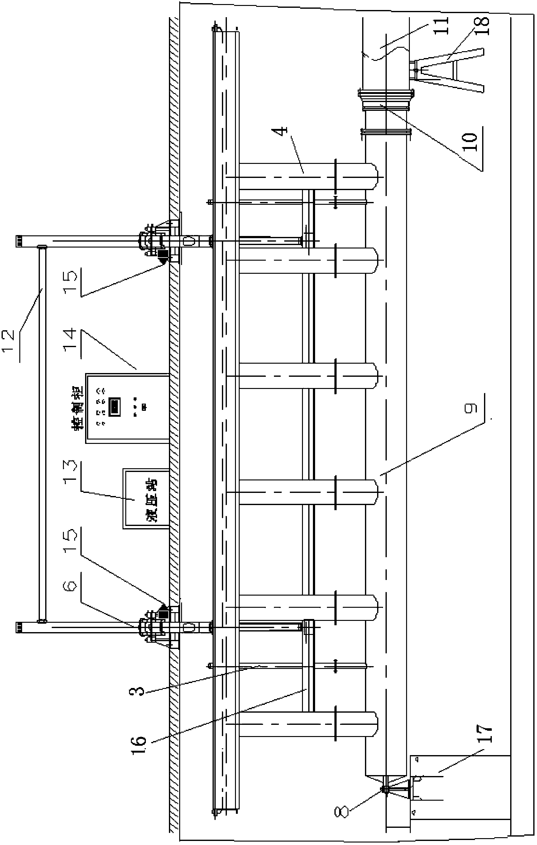
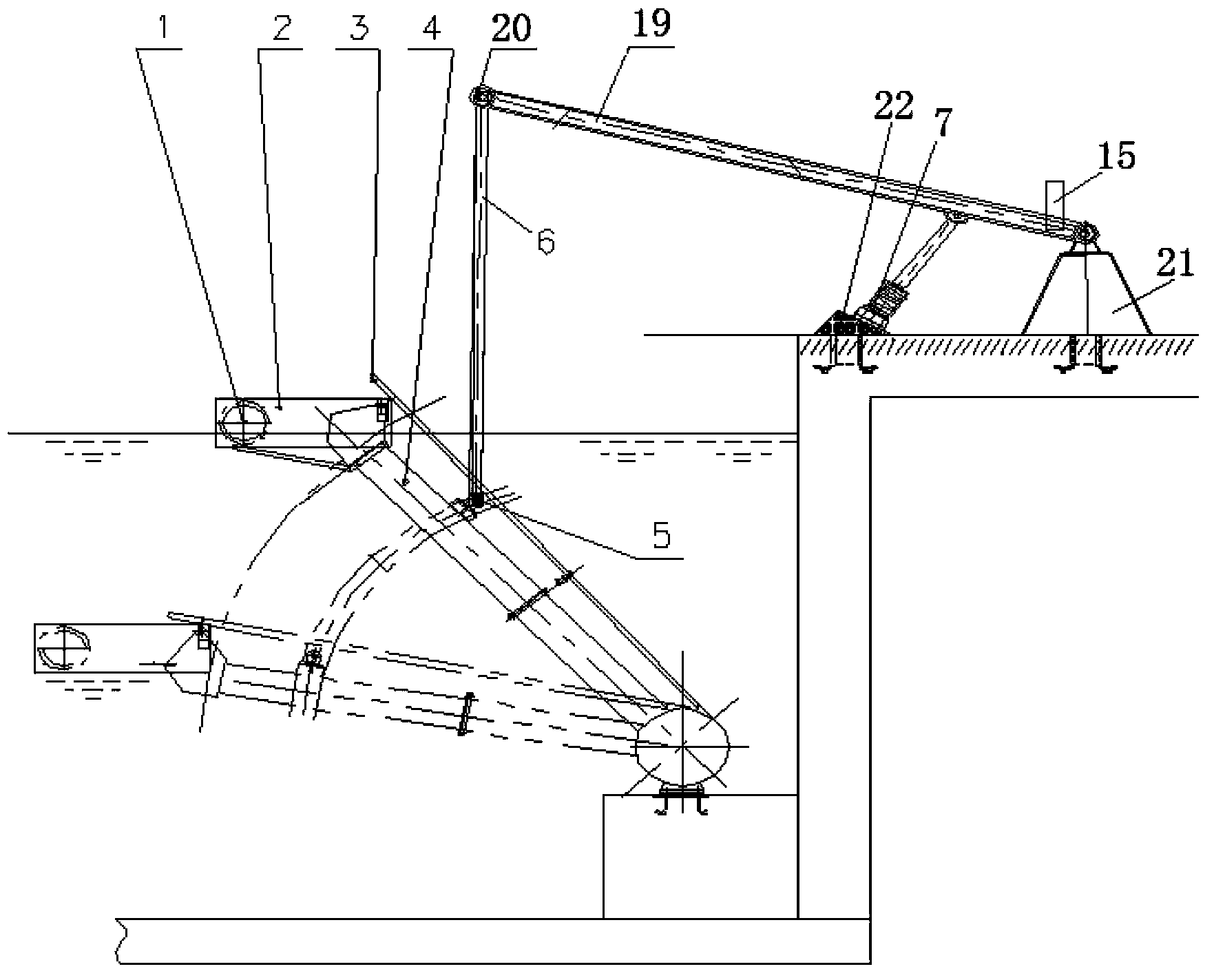
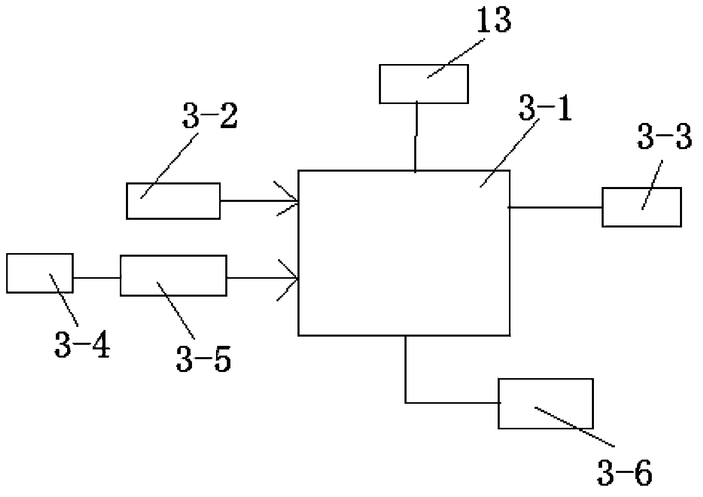
[0023] like figure 1 , 2 , shown in 3, a swivel type hydraulic push rod decanter, including 1 buoy, 2 weir grooves, 3 air outlets, 4 water outlet pipes, 5 joints, 6 rods, 7 hydraulic push rods, 8 Bearings, 9 outlet pipes, 10 pipe bearings, 11 drain pipes, 12 hanger connecting rods, 13 small hydraulic stations, 14 control cabinets, 15 angle measurement and transmission systems, 16 connecting rods, 17 supports one, 18 supports two , 19 pole two, 20 joint two, 21 hanger base, 22 hydraulic push rod base.

[0024] The rotary arm type hydraulic push rod decanter includes a buoy 1, a weir groove 2, an outlet main pipe 9, a hydraulic power device, and a hydraulic integrated control system. Setting, one end of the water outle...


PUM


Abstract

The invention discloses a spiral-arm hydraulic push-rod decanting device, which comprises a floating barrel, a weir tank, a water outlet main pipe, a hydraulic power device and a hydraulic comprehensive control system, wherein the hydraulic power device comprises a small hydraulic station, two hydraulic push rods with a position sensor and two hydraulic push rod bases, the hydraulic comprehensive control system comprises a push-rod displacement-type device oblique self-correcting interlocking alarming system and an angle-displacement device oblique self-correcting verification interlocking alarming system, the push-rod displacement-type device oblique self-correcting interlocking alarming system and the angle-displacement device oblique self-correcting verification interlocking alarming system share on control main machine with a central process unit (CPU), the angle-displacement device oblique self-correcting verification interlocking alarming system also comprises two angle measurement transmission systems, and the two angle measurement transmission systems are respectively installed on the root part of the junction of a supporting rod B of two hangers and a hanger base. The decanting depth is large, the redundant control system with the self-correcting function and the alarming and early-warning function is adopted for the control and the oblique prevention protection, and the cost is low.

Description

technical field [0001] The invention mainly relates to the field of decanting equipment, in particular to a rotary arm type hydraulic push rod decanter. Background technique [0002] In terms of sewage treatment, the decanting equipment required by the CASS process of the SBR process plays the role of discharging the supernatant that meets the standard in the pool from the weir mouth into the drain pipe on time and in quantity when the biological pool enters the drainage stage. The large-scale decanter is one of the environmental protection industrial equipment encouraged by the current state. [0003] The specific process is that the decanter descends at the set speed and follows the drop of the liquid level of the biological pool. When the weir of the decanter drops to the set position, the hydraulic push rod stops pushing (pulling), the position is maintained, and the decanter stops. descend, the drainage process ends. Then, the hydraulic push rod pushes the decanter to...

Claims


Application Information

Patent Timeline
Patent Type & Authority Patents(China)
IPC IPC(8): C02F3/12
CPCY02W10/10
Inventor 米超王淦
Owner 中节能国祯环保科技股份有限公司
Why Eureka
Try Eureka