Network element with redundant switching matrix

a network element and matrix technology, applied in the field of network elements, can solve the problems of high capital expenditure for two complete pieces of equipment, the redundancy used in prior-art network elements cannot protect against such a disaster, and the destruction of all equipment in a room, so as to achieve the effect of less hardware and lower cos

Inactive Publication Date: 2005-07-05
ALCATEL LUCENT SAS
View PDF14 Cites 13 Cited by
  • Summary
  • Abstract
  • Description
  • Claims
  • Application Information

AI Technical Summary

Benefits of technology

[0005]It is an object of the invention to provide a network element which requires less hardware and can be implemented at lower cost than conventional network elements and still provides at least partial protection against disasters such as fire, explosion, or inundation which destroy all equipment installed in a room. This object is attained by a network element for a digital communications network, comprising: a number of interface modules, a first, active switching matrix connected to the interface modules for switching paths between the interface modules, a second, redundant switching matrix also connected to the interface modules, and a controller for detecting a fault condition of the active switching matrix and for switching to the redundant switching matrix, which is then used as a new active switching matrix, wherein the interface modules are divided into two groups, and each of the two switching matrices is combined with a respective one of the groups of interface modules to form two separate units, which are interconnected by internal links, whereby the units can be installed in two separate rooms.

Problems solved by technology

It may happen, however, that as a result of fire, an explosion, or a flood disaster, all equipment in a room is destroyed and thus fails.
The redundancy used in prior-art network elements cannot protect against such a disaster, because all modules of the network element are affected by the disaster at the same time.
Its disadvantages are the high capital expenditure for two complete pieces of equipment and the size of the switching matrices that are required to ensure that even with protection mechanisms such as MSP (Multiplexer Section Protection) and SNCP (Subnetwork Connection Protection), the network elements are 100% nonblocking.

Method used


Image

  • Network element with redundant switching matrix
  • Network element with redundant switching matrix
  • Network element with redundant switching matrix

Examples


Embodiment Construction

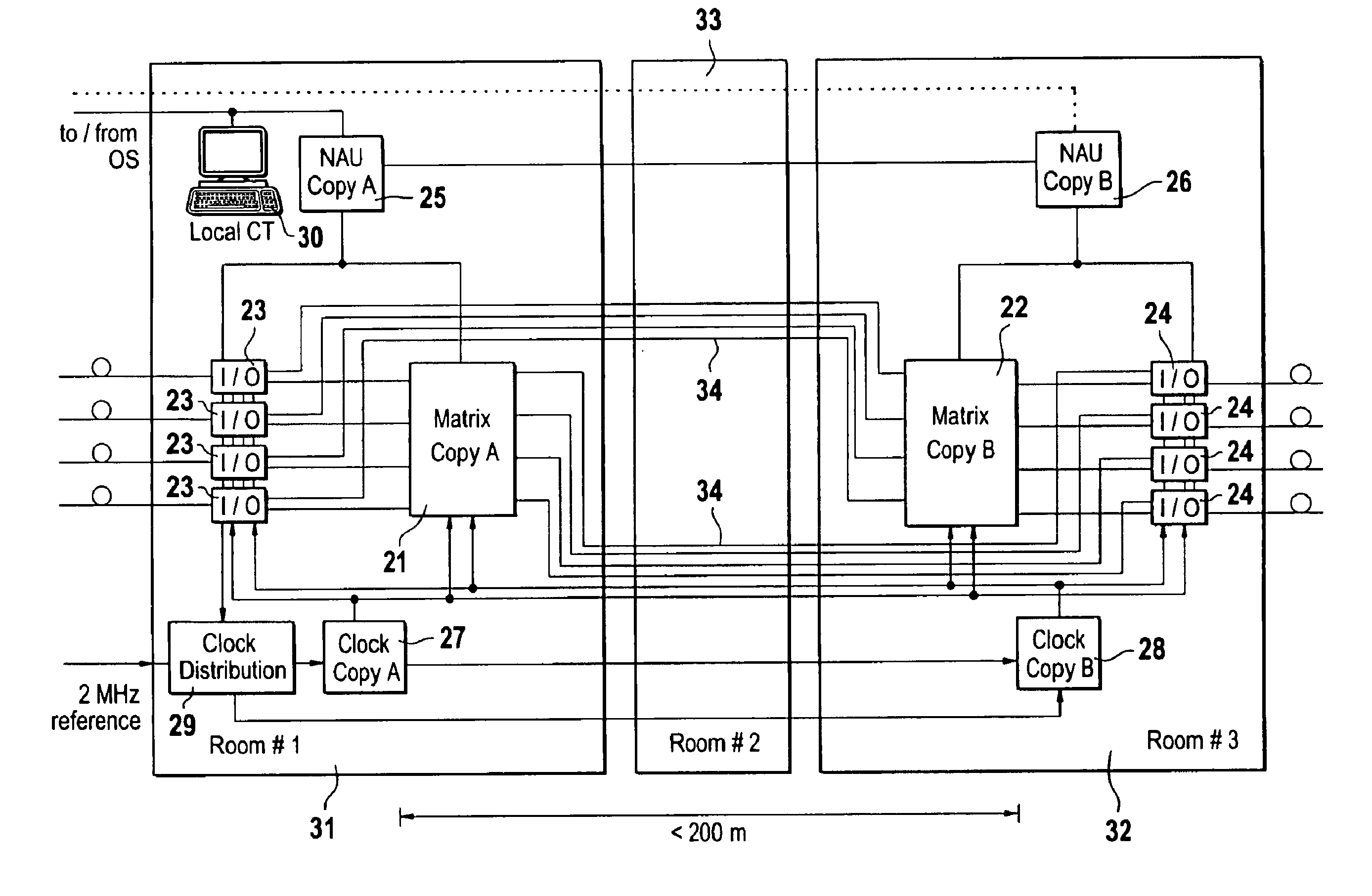
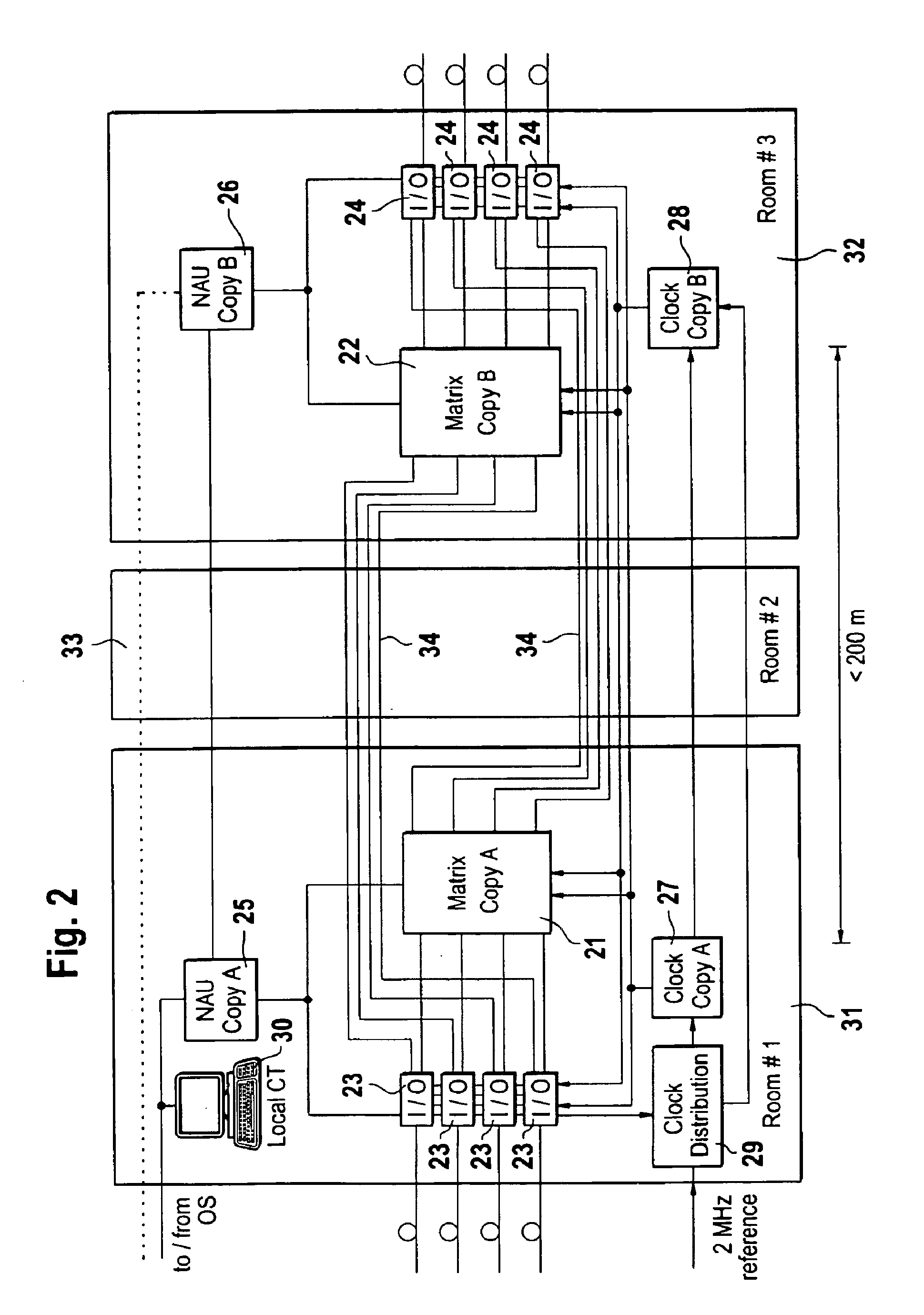
[0012]A basic idea of the invention is to install the two switching matrices, which are present anyhow, in two separate rooms, i.e., to divide a single network element between two rooms. To do this, the interface modules are divided into two groups, and each of the groups is assigned to a respective one of the switching matrices. A respective one of the switching matrices and a respective one of the groups of interface modules are arranged in, e.g., a cabinet or rack so as to form a unit, and the units are interconnected by simple internal links in such a way that both switching matrices are connected to all interface modules.

[0013]Such a network element according to the invention is illustrated in FIG. 2. It is a digital crossconnect for a synchronous digital communications network, which is designed to switch fixed paths for data transmissions within the network. The core element of the crossconnect is a switching matrix 21, 22, in which the connections between interface modules 2...


PUM


Abstract

Network elements such as digital crossconnects are provided with a 1:1 redundancy of, among other things, the switching matrix in order to maintain their functionality in the event of a hardware failure. Against disasters such as fires, explosions, or floods in which all equipment in a room is destroyed, the redundancy used in prior-art network elements can afford no protection.
To remedy this, the two switching matrices (21, 22), which are present anyhow, are installed in separate rooms (31, 32), i.e., a single network element is divided between two rooms. To this end, the interface modules (23, 24) are divided into two groups, and each of the groups is assigned to a respective one of the switching matrices. A respective one of the switching matrices and a respective one of the groups of interface modules are arranged in, e.g., a cabinet or rack so as to form a unit, and the units are interconnected by simple internal links (34) such that both switching matrices (21, 22) are connected to all interface modules (23, 24).

Description

BACKGROUND OF THE INVENTION[0001]This invention relates to a network element, particularly to a network element for a synchronous digital communications network such as SDH or SONET.[0002]Such a network element is known from an article by R. Castelli et al, “Technologie der SDH-Netzelemente: die Hardware-Plattform”, Elektrisches Nachrichtenwesen 4 / 1993, pp. 312-321. In FIGS. 9 and 10 of that article, a crossconnect for a digital communications network based on the Synchronous Digital Hierarchy (SDH) standard is shown. It has a number of interface modules and two switching matrices. Each of the switching matrices is connected to each of the interface modules and serves to switch paths between the interface modules. One of the switching matrices is always available as an active switching matrix, and the other is available as a standby matrix in the event of a failure. A controller detects a fault condition of the active switching matrix and switches to the standby matrix, which is the...

Claims


Application Information

Patent Timeline
Patent Type & Authority Patents(United States)
IPC IPC(8): H04J3/16H04Q11/04
CPCH04J3/1611H04Q11/0478H04J2203/0021H04J2203/006
Inventor KLEINE-ALTEKAMP, HARALDHEUER, VOLKMARSIGLOCH, RAINER
Owner ALCATEL LUCENT SAS
Why Eureka
Try Eureka