Detached remote sensor detection

a remote sensor and sensor technology, applied in the direction of vehicle safety arrangments, process and machine control, force/torque/work measurement apparatus, etc., can solve the problems of inability to use non-conductive packages, inability to accurately measure crash characteristics or other physical parameters, and often exposed to harsh environmental conditions. , to achieve the effect of reducing water ingress and corrosion, reducing packaging flexibility, and improving immunity to harsh automotive environmen

Inactive Publication Date: 2007-06-21
AUTOLIV ASP INC
View PDF7 Cites 15 Cited by
  • Summary
  • Abstract
  • Description
  • Claims
  • Application Information

AI Technical Summary

Benefits of technology

[0009] By using the software algorithm to determine if the sensor is detached, greater packaging flexibility is provided to the remote sensor. The additional packaging flexibility is available because the sensor no longer requires a metallic or conductive coupling surface to provide an electrical connection with the vehicle structure, required where such grounding is used to evaluate proper mounting. In addition, the sensor has improved immunity to the harsh automotive environment because water ingress and corrosion can be reduced, since electrical contact does not need to be maintained between the housing and an internal circuit board of the remote sensor. In addition, the reliability of the remote sensor is improved and false detections are reduced, because vehicle ground voltage fluctuations are not introduced into the remote sensor system by electromagnetic noise carried in the vehicle structure. Further, less hardware is required for the sensor detachment detection, thereby reducing material costs and simplifying the overall system.

Problems solved by technology

If the sensor becomes detached from the vehicle structure, an incorrect measurement of the crash characteristics or other physical parameter may result.
However, this method requires an electrical path between the sensor and the vehicle sheet metal ground, preventing the use of non-conductive packages.
Additionally, vehicles are often exposed to harsh environmental conditions.
Accordingly, corrosion or other environmental factors may affect the integrity of the electrical connection between the sensor and the vehicle structure.
In addition, the sensor would be exposed to the electrical noise introduced to the vehicle structure by the battery or other means.
Further, the presence of electrical grounding does not necessarily reflect the structural integrity of the sensor mounting.

Method used


Image

  • Detached remote sensor detection
  • Detached remote sensor detection
  • Detached remote sensor detection

Examples


Embodiment Construction

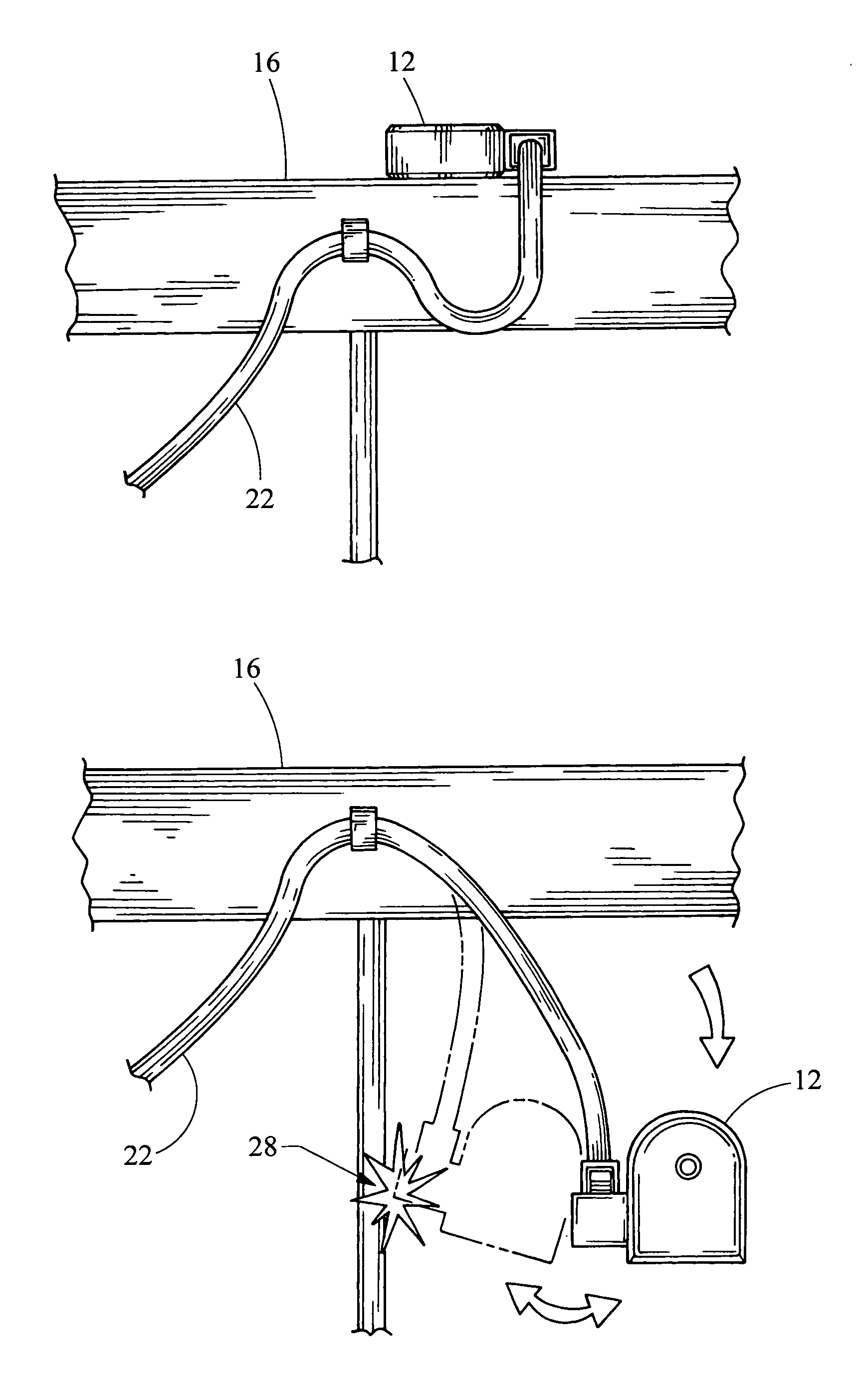
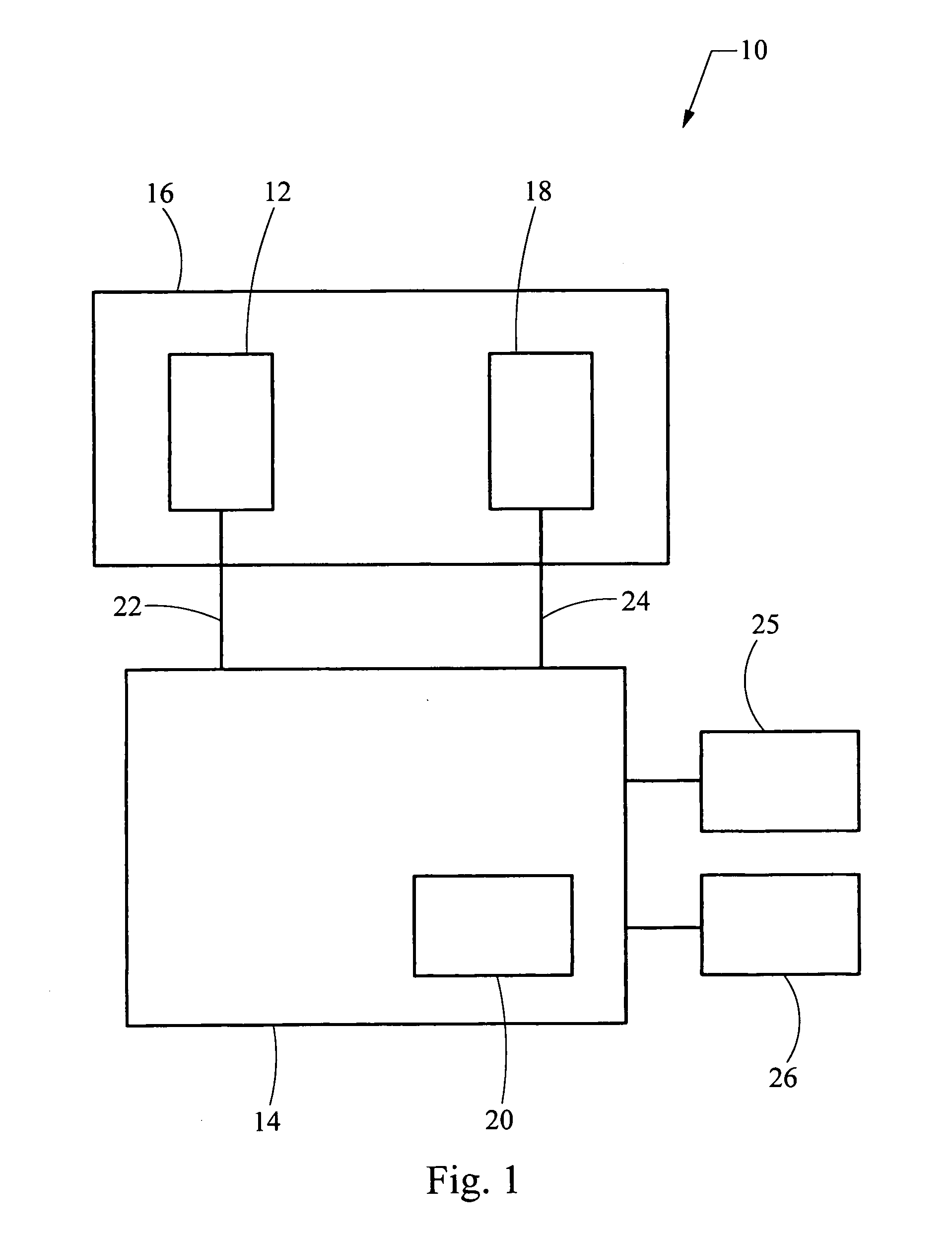
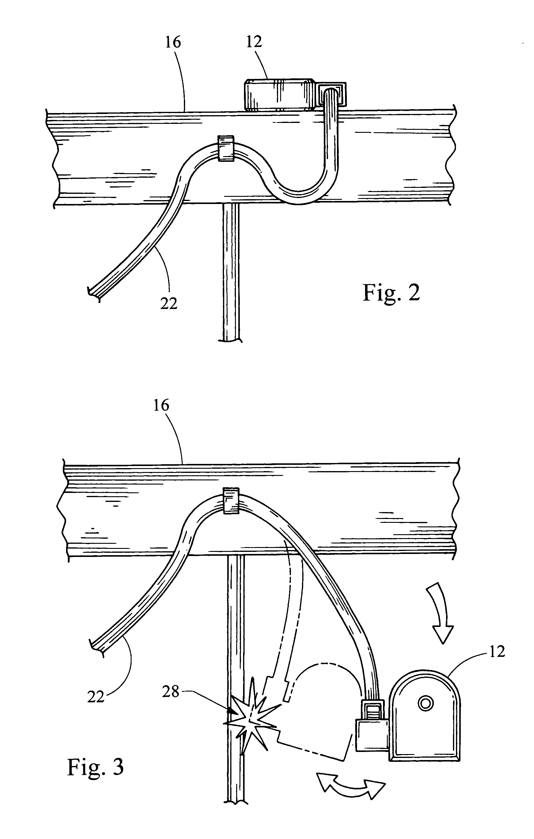
[0015] Referring now to FIG. 1, a system embodying the principles of the present invention is illustrated therein and designated at 10. The system 10 includes a sensor 12 and an electronic control unit 14. The sensor 12 is in electrical communication with the electronic control unit 14, through a wire harness 22, to provide a sensor signal indicative of vehicle characteristics. For example, the sensor 12 may be an accelerometer to provide information for a vehicle safety system prior to or during crash conditions. Accordingly, the sensor 12 is a remote sensor that is coupled to the vehicle structure 16 at a position away from the electronic control unit 14. The sensor 12 may be mounted on the vehicle structure 16 through any common attachment means including fasteners such as bolts, clips, or rivets, or through bonding such as welds or adhesive. As such, the remote sensor 12 may receive local information earlier than other sensors or in a different magnitude than other sensors locat...


PUM

PropertyMeasurementUnit
structureaaaaaaaaaa
thresholdaaaaaaaaaa
time windowaaaaaaaaaa

Abstract

A system includes a remote sensor and an electronic control unit. The electric control unit determines if the remote sensor is detached from the vehicle structure by analyzing the sensor signal from the remote sensor. The electronic control unit may compare the sensor signal to other signals. For example, from another remote sensor or an on-board sensor contained within the electronic control unit. The electronic control unit identifies features in the sensor signal indicative of the remote sensor being detached from the vehicle.

Description

BACKGROUND OF THE INVENTION [0001] 1. Field of the Invention [0002] The present invention generally relates to a system which determines when a sensor is no longer in a mounted state securely attached to the structure of a vehicle. [0003] 2. Description of Related Art [0004] Vehicle safety systems often use sensors that are located remotely from a centralized electronic control unit. Remote sensors are often located around the periphery of the vehicle and other locations to provide local information prior to and during impact. The sensed information can be used to alert the driver or deploy or operate safety systems. For example, accelerometers can provide information regarding inertial forces acting on the car prior or during impact and the severity of the impact. While the vehicle is being driven, the remote sensors continuously provide acceleration and other data to the centrally located electronic control unit. Other types of sensors can measure deflection or deformation of a ve...

Claims


Application Information

Patent Timeline
Patent Type & Authority Applications(United States)
IPC IPC(8): G01P15/00G01L3/00G01D18/00E05F15/00G08B23/00G08B21/00B60Q1/00
CPCB60R21/0132B60R2021/01006G01D3/08G01P15/00G01P21/00G01P1/026B60R21/01332
Inventor BORAN, COLMANGEL, OSCAR JR.RAKES, RICHARD JR.
Owner AUTOLIV ASP INC
Why Eureka
Try Eureka