Method and system for protecting against communication loss in an optical network system

a technology of optical network and communication loss, applied in the field of video, voice, data communication, can solve the problems of system vulnerability to service loss, more communications or services may be lost compared, prohibitive cost of ftth and fttb architecture, etc., and achieve the effect of less hardware and/or software and reduced costs

Active Publication Date: 2013-11-05
ARRIS SOLUTIONS
View PDF2 Cites 14 Cited by
  • Summary
  • Abstract
  • Description
  • Claims
  • Application Information

AI Technical Summary

Benefits of technology

[0011]According to another exemplary aspect, the secondary communication path may comprise a bandwidth that is less than a bandwidth of the primary communication path. In such an exemplary embodiment, if data communications are categorized into two different classes, such as high priority and low priority, then the secondary communication path can be designed to support only high priority data traffic when the primary communication path having a greater bandwidth than the secondary communication path becomes non-functional or inoperable for communications. In this way, the secondary communication path may have less hardware and / or software and therefore, it may have reduced costs relative to a secondary communication path which may have the exact same bandwidth as a primary communication path.

Problems solved by technology

However, in the past, the cost of FTTH and FTTB architectures have been considered prohibitive.
While the PON architecture does provide an all fiber network, it can have a few drawbacks which make such a system vulnerable to service losses.
One drawback of the PON architecture is that because of its increased capacity for bandwidth in communications, when a PON architecture experiences a physical disruption to data flow, such as in a case of a severed optical fiber, more communications or services may be lost compared if a similar break were to occur with an electrical wire supporting communications.
Usually, if communication paths are switched within this short time frame, then such switching is transparent or is not perceivable by the subscriber.

Method used


Image

  • Method and system for protecting against communication loss in an optical network system
  • Method and system for protecting against communication loss in an optical network system
  • Method and system for protecting against communication loss in an optical network system

Examples


Embodiment Construction

[0025]Referring now to the drawings, in which like numerals represent like elements throughout the several Figures, aspects of the present invention and the illustrative operating environment will be described.

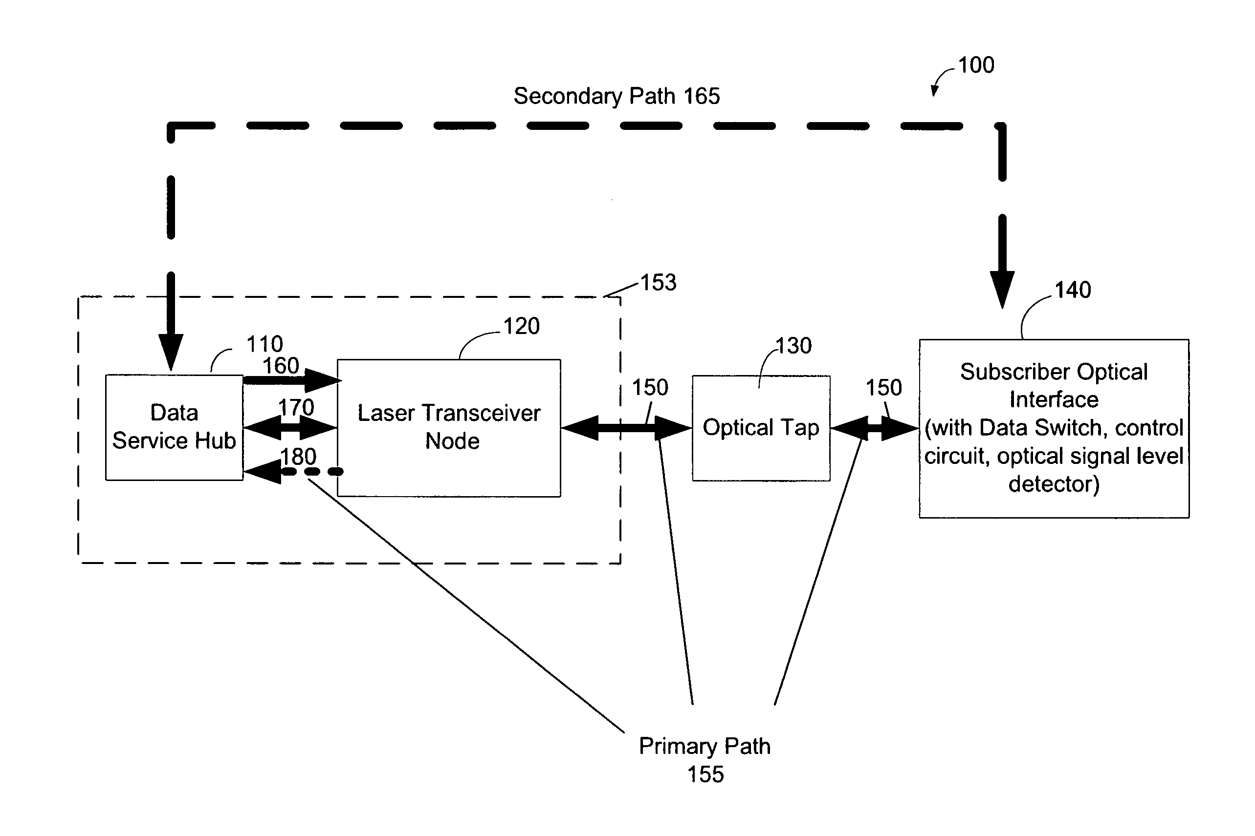
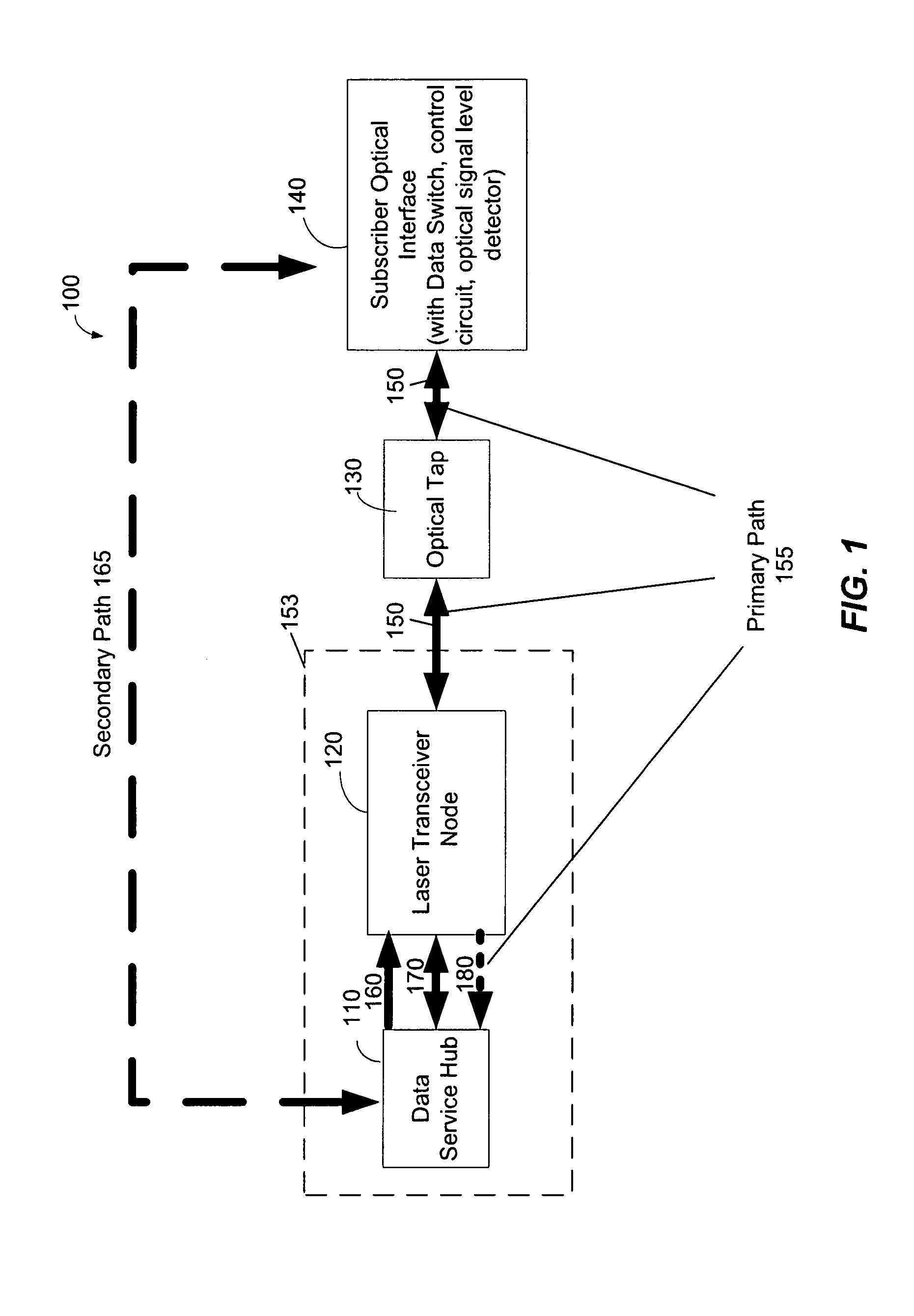
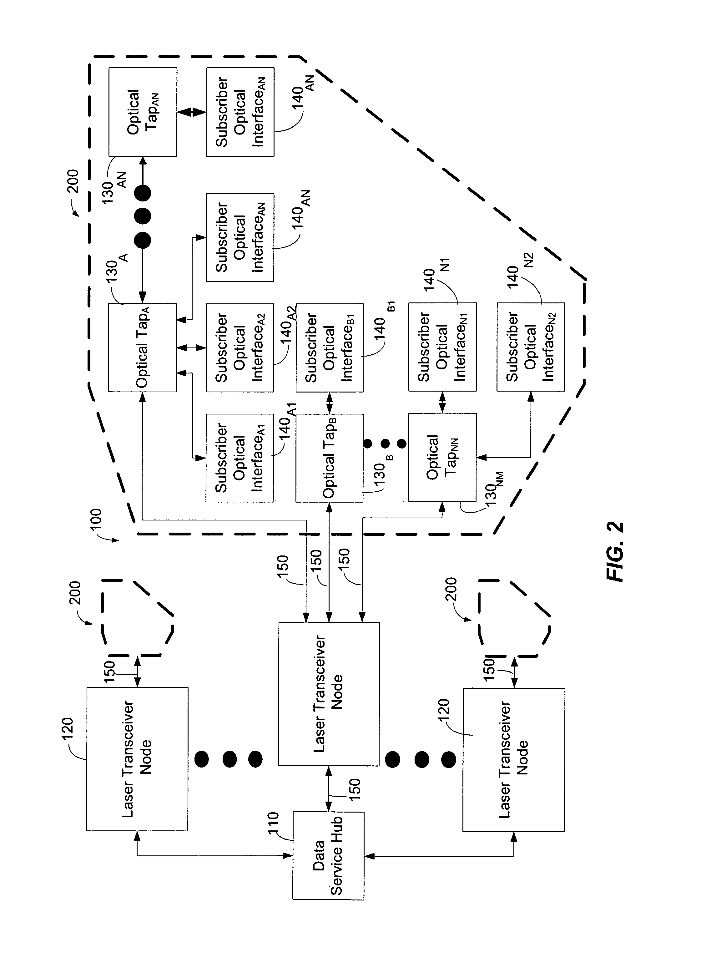
[0026]FIG. 1 is a functional block diagram illustrating an exemplary optical network architecture 100 according to the present invention. The exemplary optical network architecture 100 comprises a data service hub 110 that is connected to laser transceiver nodes 120. According to one exemplary embodiment, the laser transceiver nodes 120 are usually indoor devices and collocated with the Data Service hub 110 as indicated by dashed box 153. However, laser transceiver nodes 120 which are not collocated with the Data Service Hub 110 are not beyond the scope of the invention. The laser transceiver nodes 120, in turn, are connected to optical taps 130. The optical taps 130 can be connected to a plurality of subscriber optical interfaces 140.

[0027]Within each subscriber optical inter...


PUM


Abstract

A method and system for protecting against communication loss or disruption in an optical network system includes a signal state detector, which can measure received optical signals and determine if their strength is sufficient to support reliable communications. If the signal state detector informs the control circuit that the received optical signal is too low to support communications with the data service hub (or if there is no signal at all, such as in a severance of an optical waveguide), then the control circuit can instruct the data switch to re-route communications from the primary communication path to a secondary or back up communication path. This switching or re-routing of communications from a primary communication path which is non-functional or inoperative to an operational and fully functional communication path (a back up or secondary communication path) can be completed in a very short time, such as within fifty milliseconds or less.

Description

STATEMENT REGARDING RELATED APPLICATIONS[0001]The present application claims priority to provisional patent application entitled, “PON Protection with Fast Switching,” filed an Feb. 28, 2008 and assigned U.S. application Ser. No. 61 / 067,542; the entire contents of which are incorporated by reference.TECHNICAL FIELD[0002]The present invention relates to video, voice, and data communications. More particularly, the present invention relates to using passive optical networks (PONS) in high-reliability applications in which a subscriber is protected against a loss in communications by providing redundant communication paths between the subscriber location and a data service hub.BACKGROUND[0003]The increasing reliance on communication networks to transmit more complex data, such as voice and video traffic, is causing a very high demand for bandwidth. To resolve this demand for bandwidth, communication networks are relying more upon optical fibers to transmit this complex data. Convention...

Claims


Application Information

Patent Timeline
Patent Type & Authority Patents(United States)
IPC IPC(8): H04B10/00
CPCH04B10/032H04J14/0282H04J14/0287H04J14/029H04J14/0293
Inventor WANG, WEYL K.FARMER, JAMES O.
Owner ARRIS SOLUTIONS
Why Eureka
Try Eureka