
Rotary limiting device and lamp

A technology of rotation limit and limit ring, which is applied to lighting devices, lighting auxiliary devices, components of lighting devices, etc., can solve the problems that the rotation device does not have the function of limit, and the angle range of the rotating shaft assembly cannot be limited.

Active Publication Date: 2014-05-21
OCEANS KING LIGHTING SCI&TECH CO LTD +1
View PDF4 Cites 0 Cited by
  • Summary
  • Abstract
  • Description
  • Claims
  • Application Information

AI Technical Summary

Problems solved by technology

[0003] However, because the rotating device in the traditional technology often does not have the function of limiting, the angular range of the rotating shaft assembly cannot be limited, so that the rotating shaft assembly drives the supporting assembly to rotate more than 360 degrees or even continuously.

Method used


Image

  • Rotary limiting device and lamp
  • Rotary limiting device and lamp
  • Rotary limiting device and lamp

Examples


Embodiment Construction

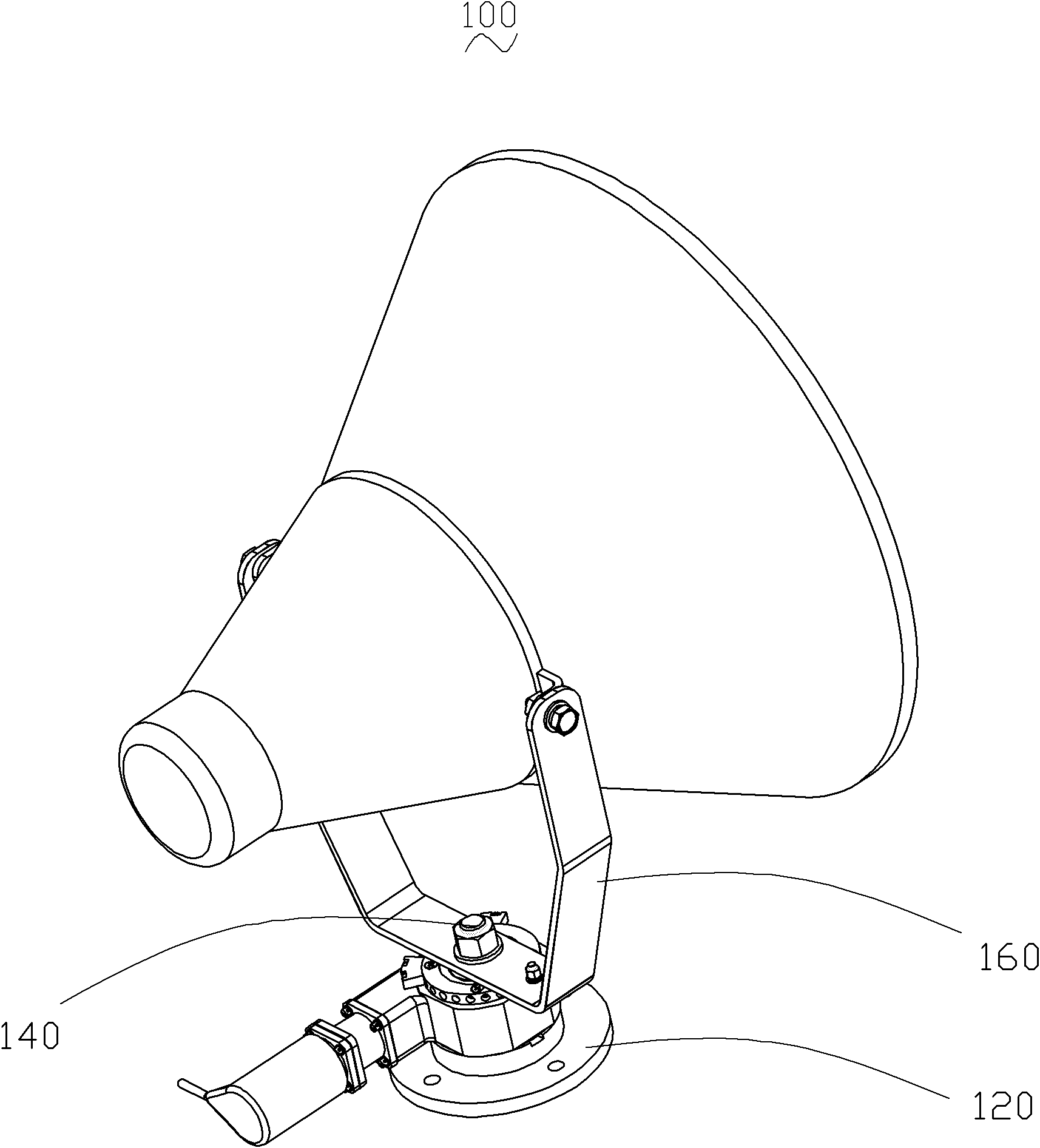
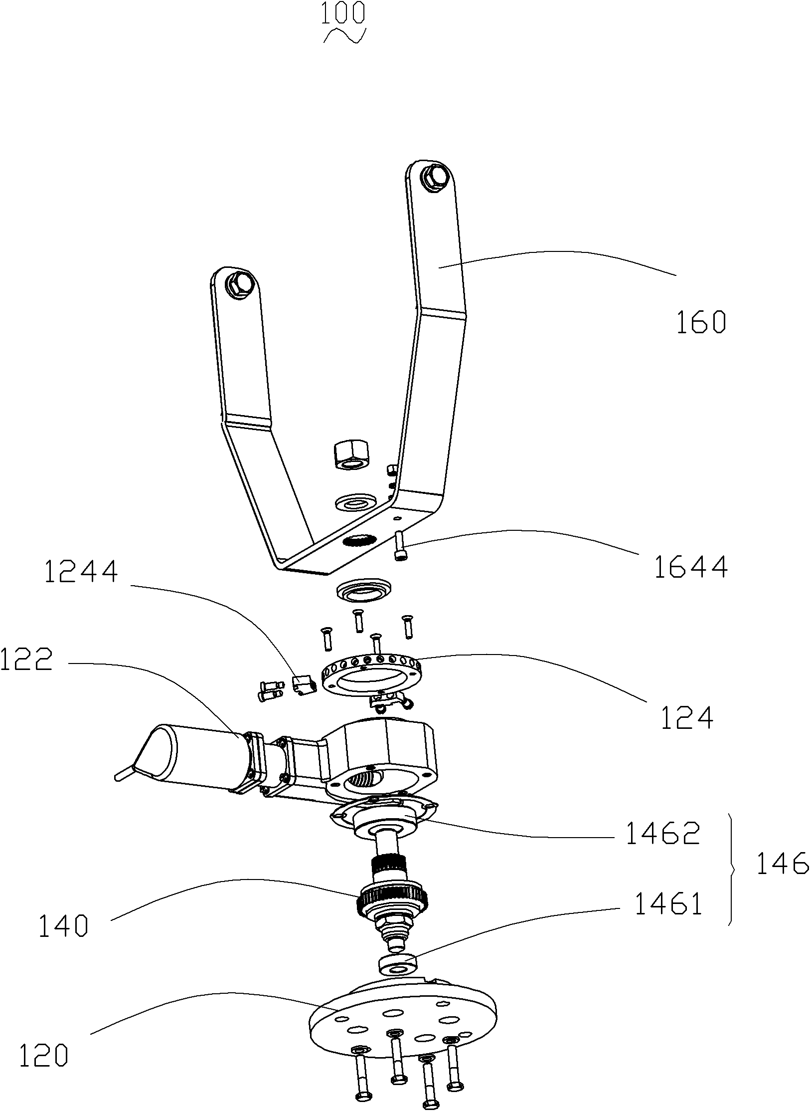
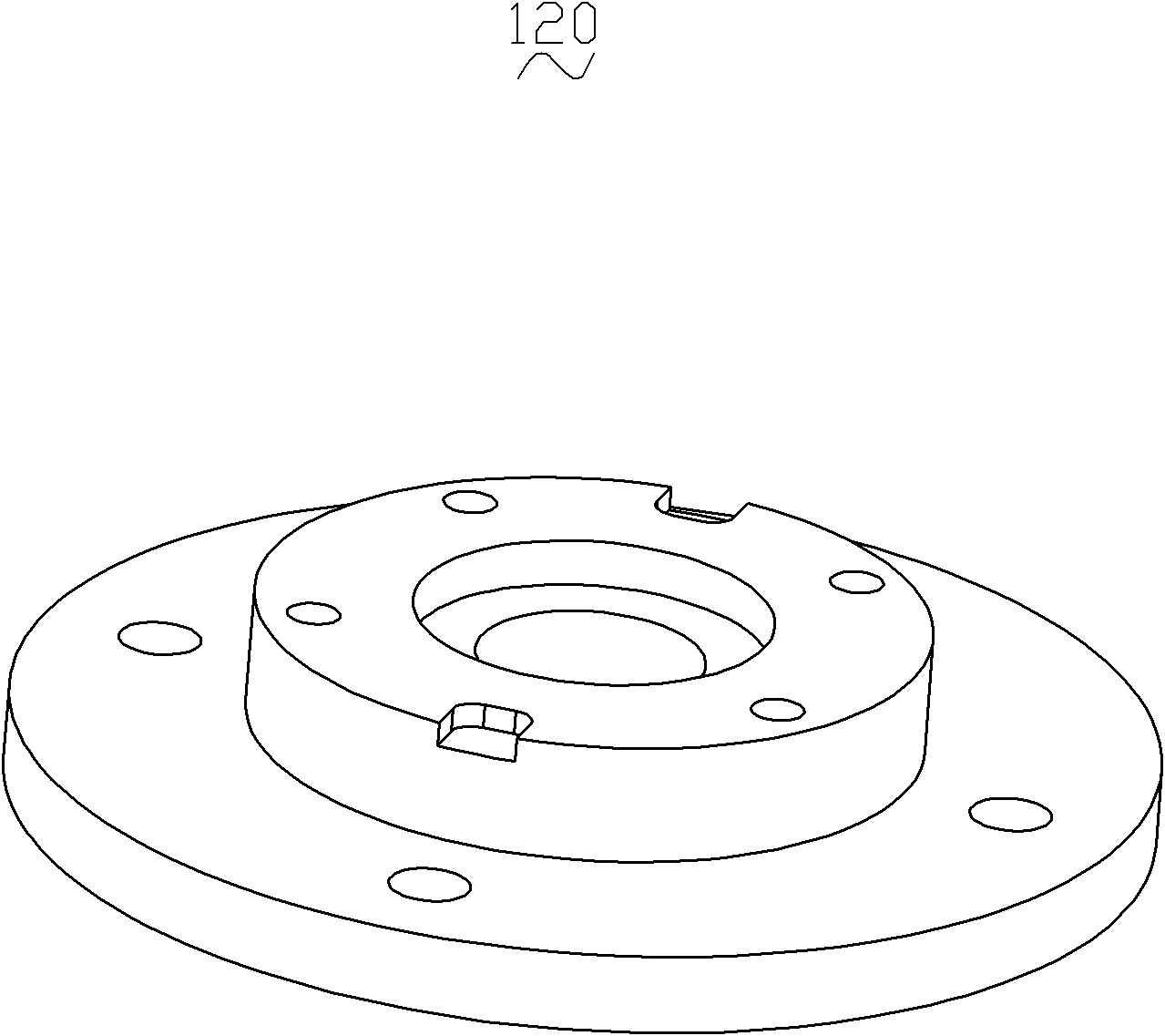
[0026] In order to solve the problem that the rotation angle range of the shaft assembly cannot be limited in the traditional technology, a new rotation limiting device capable of limiting the rotation angle of the shaft assembly is proposed. figure 1 It is an appearance structure diagram of a rotation limiting device of an embodiment. figure 2 for figure 1 An exploded structural view of the rotation limiting device in the embodiment. Such as figure 1 with figure 2 As shown, the rotation limiting device 100 includes a mounting base 120 , a rotating shaft assembly 140 connected to the mounting base 120 , and a support assembly 160 fixedly connected to the rotating shaft assembly 140 . The installation base 120 is further provided with a driving assembly 122 , the driving assembly 122 is fixed on the installation base 120 and sleeved on the rotating shaft assembly 140 . The driving assembly 122 is used to drive the rotating shaft assembly 140 to rotate, thereby further dri...


PUM


Abstract

The invention belongs to the field of mechanical rotation and discloses a rotary limiting device, which comprises an installation base, a rotating shaft component which is connected with the installation base, and a supporting component which is fixedly connected with the rotating shaft component. A driving component which is connected with the rotating shaft component is arranged on the installation base and can drive the rotating shaft component to rotate. A limiting ring is additionally arranged on the installation base. The rotating shaft component penetrates through the inner hole of the limiting ring, is fixedly connected with the supporting component and drives the supporting component to rotate. Limiting holes are arranged in the circumferential side surface of the limiting ring. A limiting block which protrudes the circumferential side surface of the limiting ring is fixedly arranged through the limiting holes. A limiting piece which protrudes the bottom of the supporting component is arranged on the supporting component and can rotate with the supporting component. The limiting block is used for limiting the rotating angle of the limiting piece. The rotary limiting device provided by the invention has the advantage that the rotating range of the supporting component is limited.

Description

【Technical field】 [0001] The invention relates to a rotation limiting device and a lamp. 【Background technique】 [0002] The rotating device in the traditional technology generally includes a support assembly, a base, and a rotating shaft assembly connecting the support assembly and the base. The rotation of the shaft assembly drives the support assembly to rotate, and then drives the carrier component fixed to the support assembly to rotate. [0003] However, because the rotating device in the conventional technology often does not have the function of limiting, the angular range of rotation of the rotating shaft assembly cannot be limited, so that the rotating shaft assembly drives the supporting assembly to rotate more than 360 degrees or even continuously. 【Content of invention】 [0004] Based on this, it is necessary to provide a rotation limiting device capable of limiting the rotation angle range of the rotating shaft assembly. [0005] A rotation limiting device,...

Claims


Application Information

Patent Timeline
Patent Type & Authority Patents(China)
IPC IPC(8): F21V21/116
Inventor 周明杰吴会利
Owner OCEANS KING LIGHTING SCI&TECH CO LTD
Learn More