
Electric reactor iron core compressing structure and electric reactor iron core compressing device

A compression structure and compression device technology, applied in the direction of transformer/inductor magnetic core, inductor/transformer/magnet manufacturing, circuits, etc., can solve the problems of poor compression effect, complicated assembly, and increased operating vibration amplitude, etc. Achieve the effect of saving processing costs, reducing safety hazards, and stable pressing force value

Pending Publication Date: 2018-09-28
SANBIAN SCI TECH
View PDF0 Cites 0 Cited by
  • Summary
  • Abstract
  • Description
  • Claims
  • Application Information

AI Technical Summary

Problems solved by technology

[0004] (1) The length of the beam itself is long and there is a certain deflection, so it is difficult to achieve the same pressing force of the iron core of the three iron core columns;
[0005] (2) The compression tooling of the beam type compression structure requires many parts, is large in size, heavy in weight, complex in assembly, takes a long time for compression, and adopts the overall surface force method, and the compression effect is poor;
[0006] (3) The compression tooling of the beam type compression structure has poor versatility and has requirements for the capacity of the reactor. For single-phase or large-capacity reactors, the length of the beam and the compression position must be increased or decreased;
[0007] (4) During the long-term operation of the compression tooling of the beam type compression structure, the amplitude of the operating vibration will increase due to the failure of the iron core cake to reach the specified pressure value or excessive compression, resulting in increased noise or loose fasteners. The fastening effect is lost, and there are potential safety hazards in the operation of the reactor

Method used


Image

  • Electric reactor iron core compressing structure and electric reactor iron core compressing device
  • Electric reactor iron core compressing structure and electric reactor iron core compressing device
  • Electric reactor iron core compressing structure and electric reactor iron core compressing device

Examples


Embodiment Construction

[0035] The present invention will be further described below in conjunction with the accompanying drawings and specific embodiments (embodiments). The specific embodiments described here are only used to explain the present invention, but not as a basis for limiting the present invention.

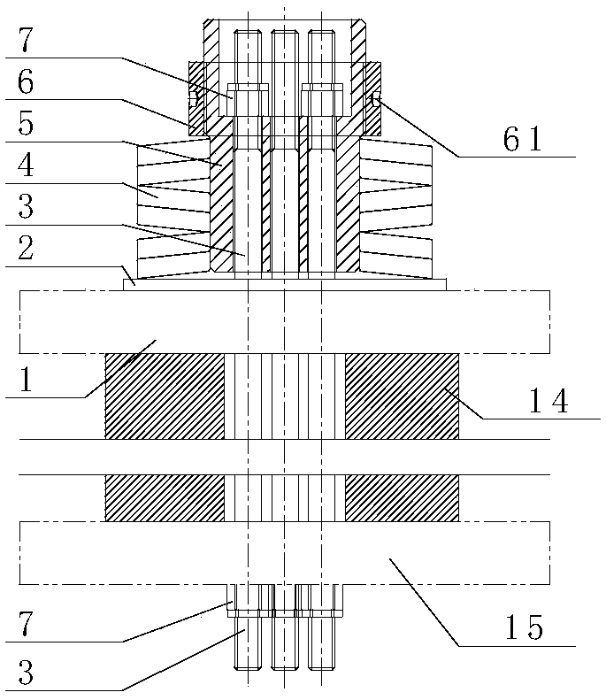
[0036] see image 3 , the reactor iron core compression structure of the present invention includes an iron core 14, an iron core upper joist 1 and an iron core lower joist 15 respectively arranged at the upper and lower ends of the iron core 14, and at least one iron core lower joist 15. The iron core 14 and the core column pull screw 3 of the iron core joist 1; the iron core upper joist 1 is provided with a pull screw sleeve 5, and the upper end of the core column pull screw 3 is pulled from the pull screw sleeve The corresponding holes on the 5 stretch out; the two ends of the stem pull screw 3 are fastened by the pull screw nut 7 respectively; the outer ring of the pull screw sleeve 5 i...


PUM


Abstract

The invention relates to an electric reactor iron core compressing structure and an electric reactor iron core compressing device, and the electric reactor iron core compressing structure comprises aniron core, an iron core upper joist and an iron core lower joist respectively located at upper and lower ends of the iron core, and at least one core limb pulling threaded rod penetrating through theiron core lower joist, the iron core and the iron core upper joist; a pulling threaded rod sleeve is arranged on the iron core upper joist; two ends of the core limb pulling threaded rod are respectively fastened by pulling threaded rod nuts; an outer ring of the pulling threaded rod sleeve is provided with a butterfly-shaped spring group in the manner of sleeving, and a boosting thread sleeve isarranged above the butterfly-shaped spring group. The electric reactor iron core compressing device comprises a connection thread sleeve connected with the pulling threaded rod sleeve through screw joint, a compressing bolt of which a lower end is connected at the thread sleeve, and a compressing sleeve and a hollow hydraulic cylinder orderly arranged on the compressing bolt in the manner of sleeving; the upper end of the compressing bolt is locked through a lock nut; and an operating window is arranged on the compressing sleeve. The electric reactor iron core compressing structure and the electric reactor iron core compressing device provided by the invention have the advantages of being simple and convenient to assemble and disassemble, providing accurate pressure, being efficient in compression, having excellent effects, being convenient to maintain, having a wide applicable range and low potential safety hazard, and so on.

Description

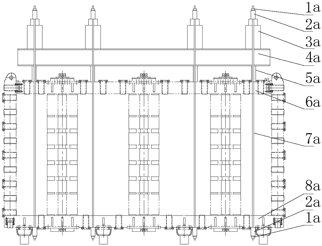
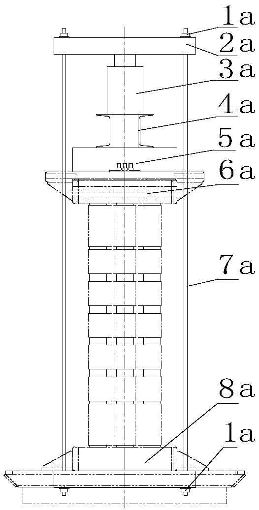
technical field [0001] The invention relates to the technical field of reactor iron core pressing, in particular to a reactor iron core pressing structure and a reactor iron core pressing device for pressing the structure. Background technique [0002] The vibration and noise generated by the reactor during use are important indicators for evaluating the key performance of the reactor, and also an important factor affecting the long-term stable operation of the reactor. Therefore, the reactor needs to be effectively compressed. [0003] see figure 1 , at present, various transformer manufacturers often adopt a beam-type compaction structure for reactor products with a discus with a voltage level of 66kV and above. The side pull screw 7a, the lower end of the pull screw 7a is covered with a skid, positioned by the nut 1a at the end of the pull screw 7a, and the upper part of the pull screw 7a is sequentially set with a skid 5a, a channel steel 4a, a hydraulic cylinder 3a, an...

Claims


Application Information

Patent Timeline
Patent Type & Authority Applications(China)
IPC IPC(8): H01F27/26H01F41/02
CPCH01F27/263H01F41/0206
Inventor 符建牛刘尚宝查银芳
Owner SANBIAN SCI TECH
Learn More