
Binary pluggable vapor cooled current lead device

Active Publication Date: 2013-01-09
INST OF ELECTRICAL ENG CHINESE ACAD OF SCI
View PDF7 Cites 11 Cited by
  • Summary
  • Abstract
  • Description
  • Claims
  • Application Information

AI Technical Summary

Problems solved by technology

However, the thermal conductivity of copper or copper alloy is very large. If the heat conduction to the low temperature area is reduced by reducing the cross-sectional area of ​​the current lead, it will inevitably increase the scorching heat of the current lead itself.
Therefore, this kind of pull-out air-cooled lead wire with a unitary structure made of copper or copper alloy generally has a large heat leakage to the low-temperature region, which increases the consumption of liquid helium during the excitation process.
Especially for conduction cooling or closed-loop running superconducting magnets with less liquid helium structure, since there is not enough liquid helium to conduct heat exchange with the current leads, the leakage heat of the current leads is likely to be conducted to the inside of the superconducting magnet, thereby causing failure of the superconducting magnet. Super, will seriously affect the performance of superconducting magnets

Method used


Image

  • Binary pluggable vapor cooled current lead device
  • Binary pluggable vapor cooled current lead device
  • Binary pluggable vapor cooled current lead device

Examples


Embodiment Construction

[0019] The present invention will be further described below in conjunction with the accompanying drawings and specific embodiments.

[0020] Such as image 3 As shown, the dual detachable air-cooled current lead device of the present invention is composed of a current lead body 13 and a primary heat exchanger 18, wherein the current lead body 13 can be pulled out from the superconducting magnet system. The primary heat exchanger 18 is fixed on the cold shield of the superconducting magnet system or on the primary cold head of the refrigerator.

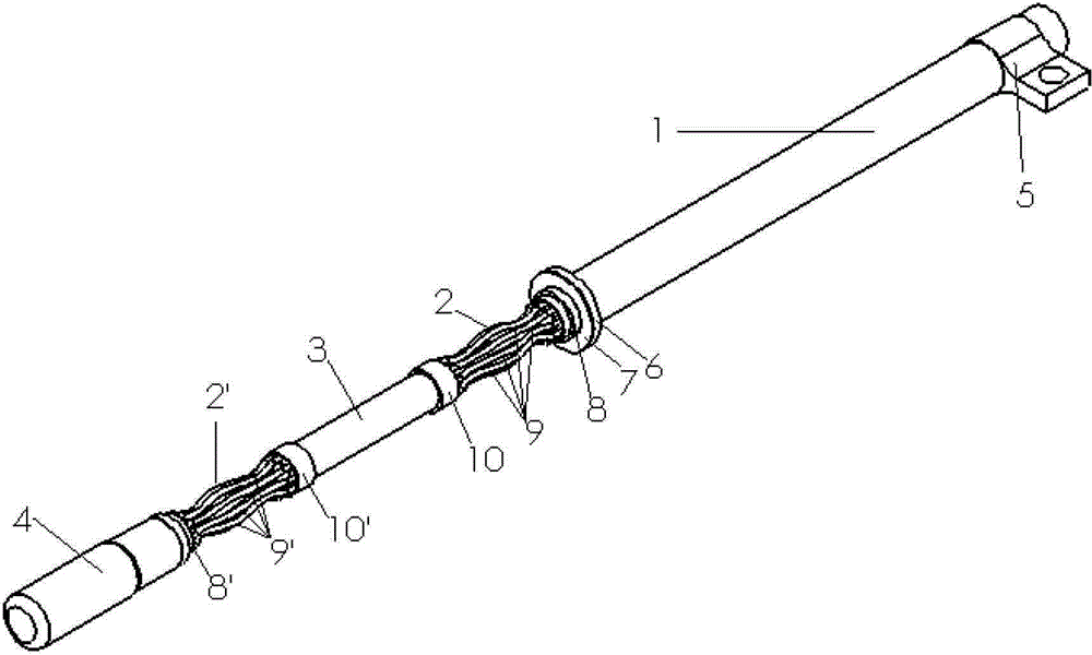
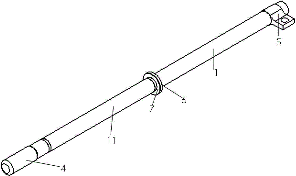
[0021] Such as figure 1 As shown, the current lead body 13 of the dual detachable air-cooled current lead device of the present invention includes a normal conduction section 1, an upper transition section 2, a high temperature section 3, a lower transition section 2' and a lead plug 4. Wherein, the constant conduction section 1 is a long tube made of copper or copper alloy material, and a terminal lug 5 is welded on the upper end o...


PUM


Abstract

The invention discloses a binary pluggable vapor cooled current lead device which comprises a current lead main body (13) and a primary heat exchanger (18). The current lead main body (13) can be plugged out from a superconducting magnet system; and the primary heat exchanger (18) is fixed on a cold shield of the superconducting magnet system or on the primary cold head of a refrigerator. An upper transition section (2) of the current lead main body (13) is connected to a normally conducting section (1) and a high temperature section (3), and a lower transition section(2') is connected to the high temperature section (3) and a lead plug (4). A support column (11) is fixed between the lower end face of the normally conducting section (1) and the upper end face of the lead plug (4) and wraps the upper and lower transition sections (2,2') and the high temperature section (3). An upper heat conducting flange (14) on the primary heat exchanger (18) is in heat contact with a heat conducting ring (6) arranged on the current lead main body(13), and intercepts the heat of the normally conducting section (1) of the current lead main body (13).

Description

technical field [0001] The invention relates to a current lead device of a superconducting magnet system, in particular to a current lead used in an MRI imaging superconducting magnet. Background technique [0002] The current lead is an important part of the superconducting magnet system, and it is the channel for the power supply at room temperature to transmit energy to the superconducting magnet in the low temperature environment of 4.2K. The current lead is the transition section from the room temperature region to the low temperature region. There are two main sources of heat introduced into the low temperature area along the current lead: leakage heat caused by heat conduction and Joule heat generated by the current flowing through the conductor. Most of the existing superconducting magnets are once excited to the target value, and then the magnet is operated under the continuous current by means of the closure of the superconducting switch. After that, the power sup...

Claims


Application Information

Patent Timeline
Patent Type & Authority Applications(China)
IPC IPC(8): H01F6/06H01F6/04G01R33/3815
Inventor 陈顺中雷沅忠程军胜王秋良
Owner INST OF ELECTRICAL ENG CHINESE ACAD OF SCI
Learn More