Grouped wave beam based multi-user precoding method and device

A multi-user, pre-coding technology, applied in the direction of digital transmission system, error prevention, electrical components, etc., can solve the problems of multi-user pre-coding algorithm complex, not simple multi-user pre-coding, etc., to achieve the effect of performance improvement

Inactive Publication Date: 2013-01-09
南通维视自动化科技有限公司
View PDF2 Cites 24 Cited by
  • Summary
  • Abstract
  • Description
  • Claims
  • Application Information

AI Technical Summary

Problems solved by technology

[0007] The present invention provides a multi-user precoding method and device based on packet beams, which are used to solve the problem in the prior art that the multi-user precoding algorithm is complex and cannot realize multi-user precoding with simplicity and high precision

Method used


Image

  • Grouped wave beam based multi-user precoding method and device
  • Grouped wave beam based multi-user precoding method and device
  • Grouped wave beam based multi-user precoding method and device

Examples


Embodiment 1

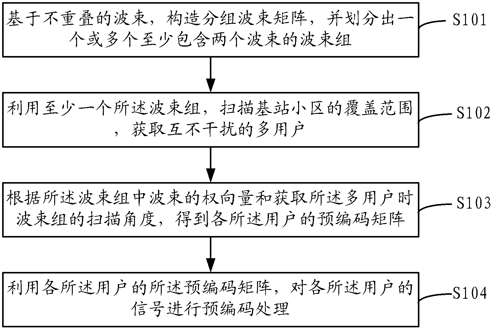
[0040] The embodiment of the present invention is applied in a multi-user MIMO (Multiple-Input Multiple-Out-put) system. The base station in the cell is configured with M transmitting antennas. The number of users in the cell is more than two, and the configurations are the same time-frequency resources. For multiple users in a single cell, the multi-user precoding method based on packet beams includes:

[0041] Step 1. Construct the packet beam matrix W s ; the matrix W s The number of rows is the number of transmitting antennas M, and the number of columns is the number of selected non-overlapping beams; the matrix W s The column vector of represents the weight vector of beam i formed by each M antenna.

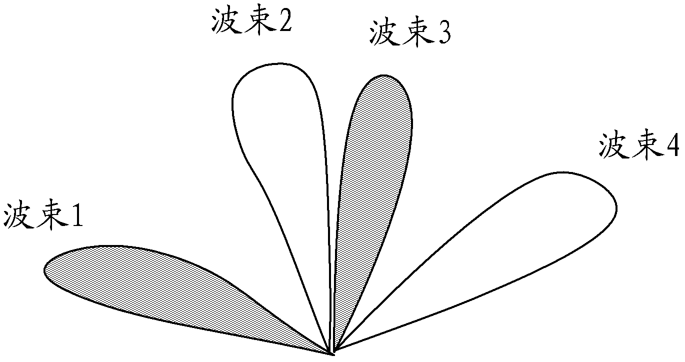
[0042] In the embodiment of the present invention, four non-overlapping beams are selected as an example for illustration, and the matrix Ws Expressed as follows: W s = w ...

Embodiment 2

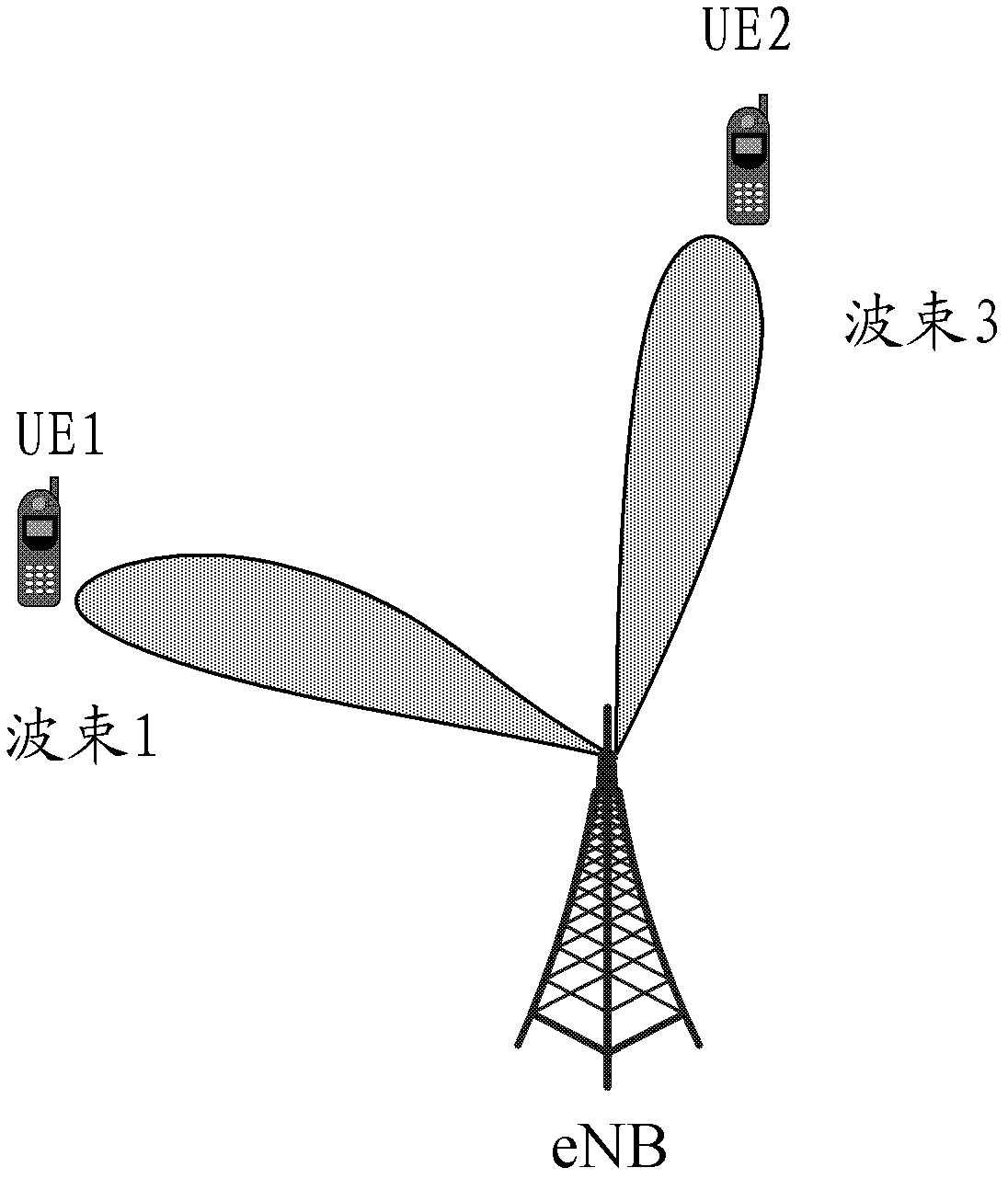
[0057] The embodiment of the present invention is a specific example based on the implementation described in Embodiment 1. In this embodiment, the number of base station transmit antennas in the cell is M=4, the eNB transmit layer of the base station is 2 layers, and the number of users is 2 , the reception of each user is 1 layer, the beams are divided into 2 groups, one group includes two beams, and the beams in the group are orthogonal, such as figure 2 As shown, the implementation steps are as follows:

[0058] Step 1. Construct the packet beam matrix W s , W s = w 11 w 12 w 13 w 14 ...

Embodiment 3

[0069] The embodiment of the present invention is still a specific example based on the implementation described in Embodiment 1. In this embodiment, the number of base station transmit antennas in the cell is M=4, the eNB transmit layer is 4 layers, and the number of users is 2 , the reception of each user is 2 layers, and the beams are 1 group. A group includes two beams, and the beams in the group are orthogonal. The specific implementation steps are as follows:

[0070] Step 1. Construct the packet beam matrix W s , W s = w 1,11 w 1,12 w 3,13 w 3,14 w ...


PUM


Abstract

The invention discloses a grouped wave beam based multi-user precoding method and a device. The method includes the following steps of: a grouped wave beam matrix is constructed based on non-overlapped wave beams, and one or more wave beam groups which at least contain two wave beams are divided up; elements in each column of the grouped wave beam matrix represent the weight vector of a first i wave beam formed by an antenna array; by the utilization of at least one wave beam group, coverage area of a base station community is scanned to acquire non-interfering multiple users, and a precoding matrix of the users is obtained according to the weight vector of the wave beam in the wave beam group and scanning angle of the wave beam group during acquisition of the multiple users; and signals of the users undergo precoding treatment by the utilization of the precoding matrix of the users. According to the method, discrete wave beam scanning is carried out by the adoption of grouped wave beams, multi-user paring users are quickly searched while the multi-user precoding matrix is also provided, and each user will not interfere with other paring users. Therefore, performance of the whole system is raised.

Description

technical field [0001] The present invention relates to the technical field of wireless communication, in particular to a multi-user precoding method and device based on packet beams. Background technique [0002] In the 3Gpp Long Term Evolution-Advanced (LTE-A) system, in order to improve the throughput and spectrum utilization of the system, the precoding technology has been further studied, and the LTE R9 version proposes to support downlink dual-stream multi-user The precoding method is actually a space division multiple access technology, but at the same time it will bring multiple access interference. [0003] A typical dual-stream precoding method mainly includes: a maximum Signal to Leakage Noise Ratio (Signal to Leakage NoiseRatio, SLNR) criterion, a maximum Signal to Noise Ratio criterion, and a maximum Signal to Interference and Noise Ratio criterion. These guidelines are actually based on such a consideration: to minimize interference to other users under the co...

Claims


Application Information

Patent Timeline
Patent Type & Authority Applications(China)
IPC IPC(8): H04L1/00
Inventor 王衍文王永强梁西安金涛
Owner 南通维视自动化科技有限公司
Why Eureka
Try Eureka