Control device of lamps for classroom

A technology for control devices and classrooms, applied in lighting devices, energy-saving control technology, electric lamp circuit layout, etc., can solve the problems of large power load, pressure, waste, etc., achieve good control and reduce power waste.

Inactive Publication Date: 2013-01-09
何振昌
View PDF0 Cites 5 Cited by
  • Summary
  • Abstract
  • Description
  • Claims
  • Application Information

AI Technical Summary

Problems solved by technology

[0002] In a classroom environment like a university, there will be multiple rows of lights in the classroom. It is troublesome to manually turn on the lights when entering the classroom, so it is necessary to invent an automatic light, but the automatic sensor lights often fail because of the sensor.

Method used


Image

  • Control device of lamps for classroom

Examples


Embodiment Construction

[0007] The present invention will be further described in detail below in conjunction with specific embodiments and accompanying drawings.

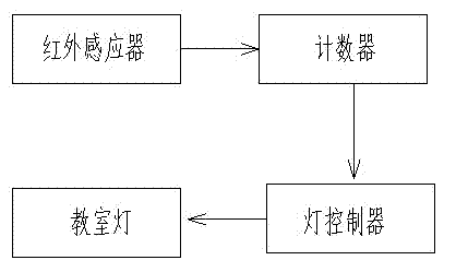
[0008] Such as figure 1 As shown, a control device for a classroom lamp includes an infrared sensor, a counter, a lamp controller and a classroom lamp, the infrared sensor is connected with a counter, the counter is connected with a lamp controller, and the lamp controller is connected with Classroom lights are connected.

[0009] Its working principle is: an infrared sensor is installed on the door of the self-study room. When someone enters, the infrared sensor senses the infrared rays of the human body and sends a signal to the counter. The counter counts the number of people entering the classroom and transmits the obtained data. For the light controller, when the light controller finds that the count of the counter exceeds a preset number, turn on the first row of lights in the classroom, and when the light controller finds that...


PUM


Abstract

The invention discloses a control device of lamps for a classroom. The control device comprises an infrared inductor, a counter, a lamp controller and classroom lamps. The infrared inductor is connected with the counter connected with the lamp controller connected with the classroom lamps. The control device saves energy, reduces unnecessary waste and well controls power utilization of classrooms in universities if used in study rooms in the universities.

Description

technical field [0001] The invention relates to a control device for classroom lamps. Background technique [0002] In a classroom environment like a university, there will be multiple rows of lights in the classroom. It is troublesome to turn on the lights manually when entering the classroom, so it is necessary to invent an automatic light, but the automatic sensing light is often because of the induction. When people enter, they will all light up, which will cause unnecessary waste in an environment with few people. At the same time, artificially controlled lights will sometimes cause unnecessary waste. For places such as schools that use large-scale electricity, it will Cause a lot of electricity load and pressure. Contents of the invention [0003] In order to overcome the above-mentioned defects, the present invention provides an automatic classroom lamp control device capable of effectively saving energy and electricity. [0004] The technical solution ado...

Claims


Application Information

Patent Timeline
IPC IPC(8): H05B37/02
CPCY02B20/40
Inventor 何振昌
Owner 何振昌
Why Eureka
Try Eureka