Pneumatic Nailer

A nail gun and pneumatic technology, applied in the field of automatic strapping equipment, can solve the problems of low work efficiency, unsafe, easy to hurt human hands, etc., and achieve the effects of improved automation, improved safety performance, and reasonable structural design.

Active Publication Date: 2015-09-16
GUANGDONG MINGHUI PNEUMATIC TECH CO LTD
View PDF9 Cites 0 Cited by
  • Summary
  • Abstract
  • Description
  • Claims
  • Application Information

AI Technical Summary

Problems solved by technology

[0002] When nailing or binding the existing pneumatic nail guns, the bundled objects are manually placed at the nozzle of the pneumatic nail gun, pressed firmly, and then nailed or tied with the pneumatic nail gun. The work efficiency is low and it is easy to injure manpower, unsafe
And the pressing part of the gun nozzle is pointed, which is easy to scratch the bundled objects, resulting in inaccurate positioning

Method used


Image

  • Pneumatic Nailer
  • Pneumatic Nailer
  • Pneumatic Nailer

Examples


Embodiment

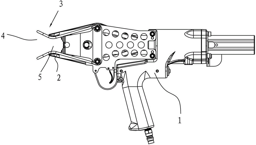
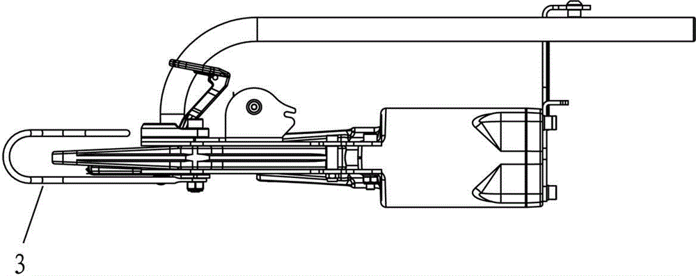
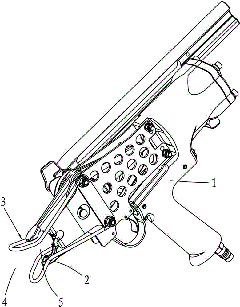
[0011] Example, combined with figure 1 and image 3 , a pneumatic nail gun, comprising a gun body 1, a nozzle 2, and a guide clip 3, the guide clip is formed by bending a metal wire, the tail end of the guide clip 3 is fixed on the gun body 1, so that the whole guide clip forms a hanging Wall structure, the head end of the guide clip 3 extends along the axial direction of the gun body 1 to the end of the gun mouth 2, and forms an outward expansion opening 4 in front of the gun mouth 2, and the guide clip 3 at the gun mouth 2 forms a clip The tight mouth 5, the distance between the clamping mouth 5 and the expansion mouth 4 expands outwards, and the clamping distance of the clamping mouth 5 is less than or equal to the maximum opening distance of the gun nozzle 2 . Compress the object through the expansion port of the guide clip and introduce it into the clamping port. Since the clearance of the clamping port is less than or equal to the maximum opening of the gun nozzle 2, th...


PUM


Abstract

The invention relates to automatic bundling equipment, in particular to a pneumatic staple gun which comprises a gun body, a muzzle and a guide clamp. The tail end of the guide clamp is fixed on the gun body, and the head end of the guide clamp extends along the axial direction of the gun body to the muzzle and forms an out-spread bellmouth in front of the muzzle. The part of the guide clamp, which is located at the muzzle, forms a clamping port; the part between the clamping port and the bellmouth spreads outside; and the clamping distance of the clamping port is not more than the maximum opening size of the muzzle. The pneumatic staple gun is reasonable in structural design and is made by adding the guide clamp to a conventional pneumatic staple gun on the basis that the structure of the conventional pneumatic staple gun remains unchanged, which provides great convenience for sorting articles before stapling or bundling the articles. The automation degree of the pneumatic staple gun is remarkably improved, the safety property is greatly improved, and the sharp clamping part of the muzzle is changed to be duckbilled with a big stress-bearing area, so the articles can be protected against scratches.

Description

technical field [0001] The invention relates to an automatic binding device, in particular to a pneumatic nail gun. Background technique [0002] When nailing or binding the existing pneumatic nail guns, the bundled objects are manually placed at the nozzle of the pneumatic nail gun, pressed firmly, and then nailed or tied with the pneumatic nail gun. The work efficiency is low and it is easy to injure Manual, not safe. And the pressing part of the gun nozzle is pointed, which is easy to scrape the bundled objects, resulting in inaccurate positioning. Contents of the invention [0003] Therefore, the object of the present invention is to provide a pneumatic nail gun that can automatically guide the bundled objects, is safe and reliable, and has significantly improved work efficiency. [0004] The purpose of the present invention is achieved like this. [0005] A pneumatic nail gun, comprising a gun body, a gun mouth, and a guide clip, the tail end of the guide clip is f...

Claims


Application Information

Patent Timeline
Patent Type & Authority Patents(China)
IPC IPC(8): B25C1/04B65B13/18
Inventor 林岳洪
Owner GUANGDONG MINGHUI PNEUMATIC TECH CO LTD
Why Eureka
Try Eureka