Conveying device

A technology of conveying device and conveyor belt, which is applied in the directions of transportation and packaging, packaging, and packaging protection. It can solve the problems of accumulation in the packing work section and the speed of manual packing cannot keep up, so as to reduce packing time and improve packing efficiency effect

Active Publication Date: 2015-07-15
GOLD HONG YE PAPER
View PDF10 Cites 0 Cited by
  • Summary
  • Abstract
  • Description
  • Claims
  • Application Information

AI Technical Summary

Problems solved by technology

[0006] Compared with the prior art, the conveying device provided by the present invention, by setting the deceleration cleaning unit on the product packing line, utilizes the oppositely arranged first brush plate and the second brush plate to clean the conveying device. The clamping and deceleration of the products to be packed in the box not only solves the problem that a large number of products to be packed are piled up in the boxing section in the prior art because the speed of manual boxing cannot keep up with the transmission speed of the products to be packaged. problem, and can also use the bristles on the surface of the first brush plate and the second brush plate to clean the dust of the product to be packaged during the transmission process, avoiding the occurrence of customer complaints caused by dust on the product surface, and further, The clamping and deceleration effect of the deceleration cleaning unit on the products to be packaged can cause the products to be packaged to gather at the deceleration cleaning unit, so that the distance between two adjacent products to be boxed on the subsequent boxing line becomes smaller, and the packing workers When packing products, more products to be packed can be carried each time. In this way, compared with the existing product transmission method, the time for packing workers to complete the packing of each case will be reduced, thereby improving Packing efficiency

Method used


Image

  • Conveying device
  • Conveying device
  • Conveying device

Examples


Embodiment Construction

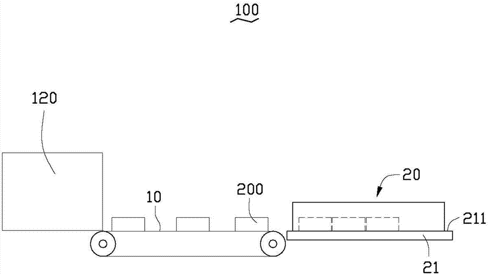
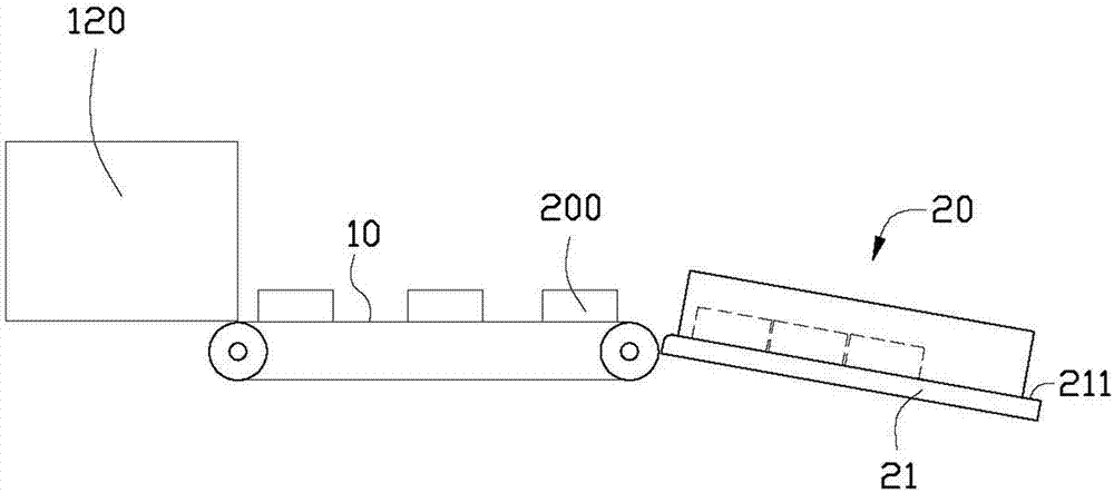
[0026] See figure 1 , The conveying device 100 provided by the embodiment of the present invention is used for conveying the product 200 to be boxed, which is packaged in a single package in the packaging section 120, to the boxing section for boxing. The conveying device 100 includes a conveyor belt 10 and deceleration cleaning Unit 20.

[0027] In this embodiment, the conveyor belt 10 is used to transport the product to be boxed 200 to the deceleration cleaning unit 20, and the product to be boxed 200 is a single pack of paper towels.

[0028] The deceleration cleaning unit 20 is used to reduce the forward speed of the product 200 to be boxed conveyed by the conveyor belt 10, and to clean the product 200 to be boxed at the same time.

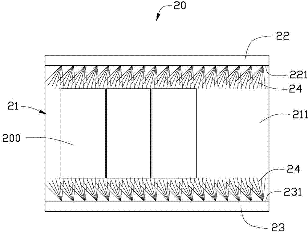
[0029] Such as figure 2 As shown, the deceleration cleaning unit 20 includes a carrying plate 21 and a first brush plate 22 and a second brush plate 23 arranged on opposite sides of the carrying plate 21 along the extending direction of the carrying...


PUM


Abstract

The invention relates to a conveying device which comprises a conveyor belt and a speed-reduced cleaning unit, wherein the speed-reduced cleaning unit comprises a bearing plate, a first hairbrush plate and a second hairbrush plate, wherein the first hairbrush plate and the second hairbrush plate are arranged on the opposite sides of the bearing plate, the bearing plate is provided with a bearing surface for bearing products to be encased with certain kinetic energy and conveyed by the conveyor belt, the first hairbrush plate is provided with a first bristle surface, and bristles are formed on the surface of the first bristle surface, the second hairbrush plate is provided with a second bristle surface, and bristles are formed on the surface of the second bristle surface, the first bristle surface and the second bristle surface are arranged opposite to each other, and a channel for products to be encased is defined by the first bristle surface, the second bristle surface and the bearing surface so as to enable products to be encased to pass through, and the first bristle surface and the second bristle surface are used for carrying out frictional speed reduction and cleaning on products to be encased when the products to be encased pass through the channel. Compared with the prior art, the conveying device not only can avoid that an encasing workshop section has an accumulation phenomenon because the conveying speed of products to be encased is overquick, and can carry out dust cleaning on products to be encased.

Description

Technical field [0001] The invention relates to a conveying device, in particular to a conveying device for conveying products in the process of product packing. Background technique [0002] Usually, in the last section of the factory, the products need to be boxed to facilitate the storage and transportation of the products. In traditional production lines, the finished products are usually conveyed to the packaging workbench at the end of the assembly line through a conveyor belt, and then the products are manually packed. [0003] Generally speaking, the speed of manual packing depends on the proficiency and physical condition of the packing workers. Therefore, in some cases, the packing speed of the packing workers may not keep up with the conveying speed of the products. At this time, a large number of products to be packed will be piled up on the packaging workbench. In addition, when the products to be packed are transported to the packaging workbench, the floating dust i...

Claims


Application Information

Patent Timeline
Patent Type & Authority Patents(China)
IPC IPC(8): B65B35/44B65B55/00
Inventor 王亚娟
Owner GOLD HONG YE PAPER
Why Eureka
Try Eureka