
Scramjet engine flame stabilizing device with front edge air cleft structure

A scramjet and flame stabilization technology, applied in ramjet engines, mechanical equipment, etc., can solve the problems of poor air mixing effect, mainstream air mixing, and less material and energy exchange, and achieve enhanced mixing effect and flow loss Small, small effect of flow field

Active Publication Date: 2014-12-03
BEIHANG UNIV
View PDF6 Cites 0 Cited by
  • Summary
  • Abstract
  • Description
  • Claims
  • Application Information

AI Technical Summary

Problems solved by technology

However, the fluted flame stabilizer is a wall flame stabilizing device, the flow field in the fluted is relatively "closed" relative to the mainstream, and the material and energy exchange inside and outside the fluted is less, so there is a problem of mixing with the mainstream air
In order to improve the mixing characteristics of the fluted flame stabilizer, the researchers tried to increase the thickness of the fluted shear layer by setting the fuel nozzle or the spoiler to increase the mass exchange rate between the fluted gas flow and the mainstream, but these methods will Introduce additional total pressure loss, affect the flow of air flow in the groove, and may have a negative impact on the flame stabilization performance of the groove
To sum up, the traditional fluted flame stabilizer has the problems of poor air mixing effect and small flame propagation range while stabilizing the flame

Method used


Image

  • Scramjet engine flame stabilizing device with front edge air cleft structure
  • Scramjet engine flame stabilizing device with front edge air cleft structure
  • Scramjet engine flame stabilizing device with front edge air cleft structure

Examples


Embodiment Construction

[0019] The present invention will be described in detail below in conjunction with the accompanying drawings and specific embodiments.

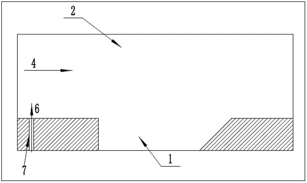
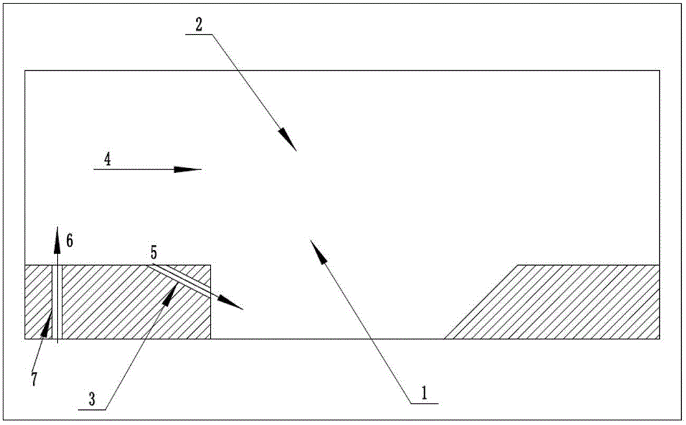
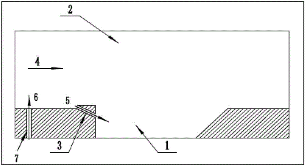
[0020] The present invention firstly provides an embodiment without a front-end fuel nozzle. Since the fuel supply varies under different pressure conditions, the embodiment of the present invention is carried out under two pressure conditions, namely 0.81MPa and 1.21MPa. Wherein, the structures of the main flow channel 2 of the super-combustion combustion chamber and the super-combustion groove flame stabilizer 1 are the same as those of the traditional groove flame stabilizer, and the groove leading edge gas is introduced into the front end of the super-combustion groove flame stabilizer 1 of the H0 and H1 structures. Slit 3, the airflow 4 of the main channel of the super-combustion combustion chamber enters the super-combustion groove flame stabilizer 1 through the air gap 3 at the front edge of the groove, so as to increase the mass exchan...


PUM


Abstract

The invention provides a scramjet engine flame stabilizing device with a front edge air cleft structure. A groove front edge air cleft structure is introduced on the device on the basis of the scramjet engine flame stabilizing device, namely, the front edge of a groove is provided with an inclined joint so as to communicate a groove front flow channel with a groove inner flow field. The introduction of the groove front flow channel drives airflow on the neighborhood of the wall surface of a flow channel to enter the groove through the inclined joint, and the gas flow inside the groove is amplified. The a fuel spout is formed in front of front of the groove, and the existence of air cleft structure can introduce part of fuel in the groove; and the retention time of a fuel is increased and the inner and outer mixing actions of the groove are strengthened, and the normal operation of a flame stabilizer of the groove is guaranteed.

Description

technical field [0001] The invention relates to the technical field of scramjet engines, in particular to a scramjet flame stabilizing device with a leading edge air slot structure, which is an optimized design of the traditional groove flame stabilizer in the combustion chamber. Background technique [0002] Scramjet engines have high specific impulse at high Mach numbers. In the super-combustion chamber, the flow velocity is very high, and the residence time is only a few milliseconds. It is very difficult to complete the mixing, ignition and combustion of fuel in such a short time, so it is necessary to introduce appropriate flame stabilization measures. In recent years, the fluted structure has received extensive attention as a flame stabilization method integrating flame stabilization, mixing enhancement, and fuel matching. In the 1990s, the Russian Central Aeronautics Agency (CIAM) applied the grooved flame stabilizer device in the scramjet engine. The device forms a...

Claims


Application Information

Patent Timeline
Patent Type & Authority Patents(China)
IPC IPC(8): F02K7/10
Inventor 刘玉英金劲睿洪燕
Owner BEIHANG UNIV
Learn More