
Ball valve with a valve seat having functions of auto-cleaning and dust proofing

A functional valve and self-cleaning technology, which is applied in the direction of valve devices, cocks including cut-off devices, engine components, etc., can solve problems such as non-self-cleaning, piston rings cannot move normally or difficult to move, spring elastic failure, etc., to increase reliability performance and service life, reduce maintenance and shutdown frequency, and ensure long-term trouble-free operation

Inactive Publication Date: 2013-01-16
KAIRUITE VALVE
View PDF10 Cites 1 Cited by
  • Summary
  • Abstract
  • Description
  • Claims
  • Application Information

AI Technical Summary

Problems solved by technology

If the above-mentioned ball valve is used under the harsh working conditions of high-pressure media containing impurities and particles, the following situations will occur: 1. The impurities or particles in the medium will enter the spring chamber of the valve seat, causing the spring to fail elastically or fail to move, resulting in the valve The sealing surface of the seat cannot be against the spherical surface of the valve core to cause the valve to leak; 2. Impurities or particles in the medium will gather at the end of the piston ring of the valve seat, and after the valve has been used for a period of time, it will appear due to the accumulation As a result, the piston ring cannot move normally or is difficult to move, so that the valve is stuck during operation and the valve operation fails; 3. The inner and outer edges of the valve seat sealing surface are prone to accumulation of aggregates, which cannot be self-cleaned, resulting in premature damage to the valve seal , shorten the service life of the valve

Method used


Image

  • Ball valve with a valve seat having functions of auto-cleaning and dust proofing
  • Ball valve with a valve seat having functions of auto-cleaning and dust proofing

Examples


Embodiment Construction

[0012] The relevant details and working principles of specific embodiments of the present invention are described in detail below in conjunction with the accompanying drawings:

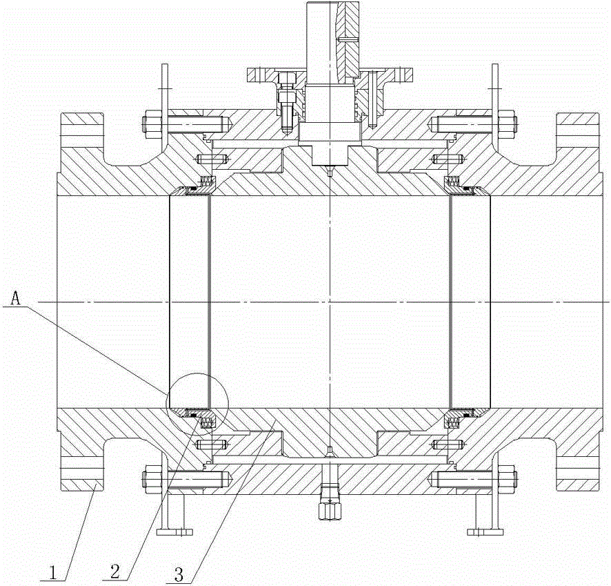
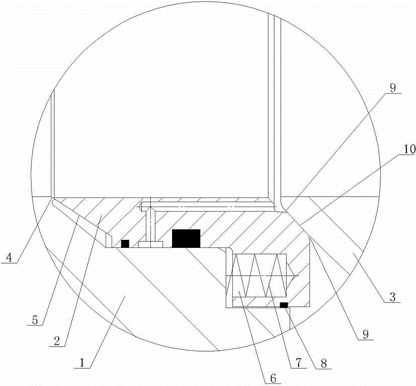
[0013] As shown in the figure, the ball valve with a self-cleaning and dust-proof valve seat of the present invention includes a valve body 1, a spherical valve core 3 and a valve seat 2. The valve seat 2 is a piston ring structure, and the piston ring is movable on the valve body 1. In the piston cavity, the piston ring is provided with a spring chamber 6, and a spring 7 is provided in the spring chamber 6. Under the action of the spring 7, the sealing surface 10 of the piston ring is against the spherical surface of the spherical valve core 3, and the piston ring is provided with one end of the sealing surface. There is a seal ring 8 between the piston cavity and the piston cavity. An elastic cone seal is provided between the end of the piston ring without a sealing surface and the piston cavity. The...


PUM


Abstract

The invention discloses a ball valve with a valve seat having functions of auto-cleaning and dust proofing. The ball valve comprises a valve body, a spherical spool and the valve seat. The valve seat is in a piston ring structure. A piston ring is movably disposed in a piston cavity of the valve body. The piston ring is provided with a spring chamber. A spring is disposed in the spring chamber. A seal face of the piston ring is abutted to a spherical face of the spherical spool under the action of the spring. The ball valve is characterized in that a seal ring is disposed between one end, with the seal face, of the piston ring and the piston cavity for sealing. An elastic conical face is disposed between one end, without the seal face, of the piston ring and the piston cavity for sealing. Small grooves are arranged on the inner edge and the outer edge of the seal face of the piston ring. The valve seat has the functions of auto-cleaning and dust proofing, and has that advantages that long-term failure-free operation is guaranteed, reliability is improved, service life is prolonged, maintenance and overhauling frequency is reduced, and the valve seat is especially suitable for harsh work conditions of high pressure and work conditions in the presence of media such as impurities and particles.

Description

technical field [0001] The invention relates to a valve, in particular to a ball valve with a self-cleaning and dust-proof valve seat. Background technique [0002] In the prior art, ball valves are only suitable for high-purity liquid or gaseous media without impurities, and the scope of application of the product is limited. If the above-mentioned ball valve is used under the harsh working conditions of high-pressure media containing impurities and particles, the following situations will occur: 1. The impurities or particles in the medium will enter the spring chamber of the valve seat, causing the spring to fail elastically or fail to move, resulting in the valve The sealing surface of the seat cannot be against the spherical surface of the valve core to cause the valve to leak; 2. Impurities or particles in the medium will gather at the end of the piston ring of the valve seat, and after the valve has been used for a period of time, it will appear due to the accumulatio...

Claims


Application Information

Patent Timeline
IPC IPC(8): F16K5/20F16K5/08
Inventor 李运龙邱志忠
Owner KAIRUITE VALVE
Learn More