
Prestack depth migration method under condition of undulating surface

A technology of pre-stack depth migration and undulating surface, applied in seismic signal processing and other directions, can solve problems such as poor effect, unstable calculation, huge data and extra calculation

Active Publication Date: 2013-01-23
PETROCHINA CO LTD
View PDF3 Cites 25 Cited by
  • Summary
  • Abstract
  • Description
  • Claims
  • Application Information

AI Technical Summary

Problems solved by technology

In order to solve the error caused by the elevation static correction time shift, the non-horizontal observation surface is changed into a horizontal observation surface, so that the conventional migration operator can be used for wave field continuation, and migration can be done conveniently. Beasley and Lynn in 1992 The concept of "zero-velocity layer" is proposed, and a virtual layer with a small velocity is inserted between the undulating surface and the datum surface, which can also eliminate the influence of the undulating surface, but the calculation is unstable in the case of large undulations, and the effect is poor
Both the "direct extension" method based on the depth extrapolation operator of the wave equation applied by Yang et al. in 1999 and the "wave field upward extension" method applied by He Ying et al. The reference velocity makes the migration accuracy insufficient, and the structural imaging near the shallow undulating surface is partially covered by noise
In 2008, Shragge proposed the wave field continuation in the Riemann coordinate system, and defined the coordinate system as similar to the undulating surface, so that the traditional migration method can be applied, but due to the need for regularization such as interpolation of the data, it is often requires a huge amount of extra computation

Method used


Image

  • Prestack depth migration method under condition of undulating surface
  • Prestack depth migration method under condition of undulating surface
  • Prestack depth migration method under condition of undulating surface

Examples


Embodiment Construction

[0031] In order to make the purpose, technical solutions and advantages of the embodiments of the present invention more clear, the embodiments of the present invention will be further described in detail below in conjunction with the accompanying drawings. Here, the exemplary embodiments and descriptions of the present invention are used to explain the present invention, but not to limit the present invention.

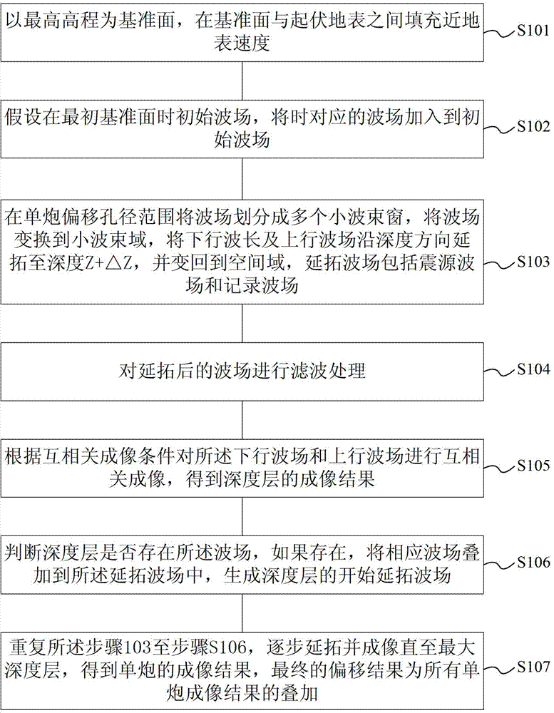
[0032] Such as figure 1 As shown, the present invention provides a method for pre-stack depth migration under undulating surface conditions, the method includes the following steps:

[0033] Step S101: Take the highest elevation as the reference plane z beg =0, the near-surface velocity is filled between the datum and the undulating surface.

[0034] Step S102: Assume that in the initial reference plane z beg = 0, the initial wave field u(x,z beg )=0, the actual geophones and sources are distributed on the undulating surface, and the recorded wave field is u e (x...


PUM


Abstract

The invention discloses a prestack depth migration method under a condition of an undulating surface. The prestack depth migration method under the condition of the undulating surface comprises the follows: a step 1 of filling a near-surface velocity between a reference surface and the undulating surface by regarding the highest elevation as a reference surface zbeg=0; a step 2 of adding a corresponding when the wave field zbeg=z=0 into an initial wave field providing that the initial reference surface zbeg=0; a step 3 of dividing the wave field in a range of a single-shot migration aperture into multiple small wave beam windows, converting the multiple wave beam windows to small wave beam regions, and respectively extending a downlink wave field and an uplink wave field to a depth z+deltaz along a depth direction; a step 4 of performing filtration treatnmetn on the extended wave fields; a step 5 of performing cross-correlation imaging by applying the downlink wave field and the uplink wave field based on the cross-correlation imaging condition to obtain an imaging result of the depth layer z+deltaz; a step 6 of judging if a wave field exists in the depth layer z+deltaz, if so, adding a corresponding wave field to the extended wave field to generate an initial extension wave field of the depth layer z+deltaz; and a step 7 of repeating the step 3 to step 6 and gradually extending and imaging until reaching a maximum depth layer zmax so as to obtain an imaging result of the single shot.

Description

technical field [0001] The invention relates to a pre-stack depth migration imaging technology in the field of seismic data processing in oil exploration, in particular to a pre-stack depth migration method under undulating surface conditions. Background technique [0002] With the continuous development of seismic exploration technology, the strategic focus of my country's oil and gas exploration is gradually shifting to areas with complex geological conditions. However, for areas with complex geological conditions, such as areas with complex surface conditions such as the mountainous areas in western China, conventional seismic data processing based on horizontal stacking has encountered great difficulties. Conventional elevation static correction can solve the influence of undulating surface, but the realization of this method is based on the assumption of surface consistency, only when the surface undulation is not large, the lateral change of the low-velocity zone is sl...

Claims


Application Information

Patent Timeline
IPC IPC(8): G01V1/28G01V1/36
Inventor 叶月明庄锡进胡冰
Owner PETROCHINA CO LTD
Learn More