Coupler for electrical appliances with identification function

A technology for identification and couplers, which is applied in the direction of coupling devices, circuits, electrical components, etc., and can solve problems such as single functions

Inactive Publication Date: 2015-12-30
董晓波
View PDF7 Cites 0 Cited by
  • Summary
  • Abstract
  • Description
  • Claims
  • Application Information

AI Technical Summary

Problems solved by technology

The above-mentioned electric kettle coupler has the defect of single function

Method used


Image

  • Coupler for electrical appliances with identification function
  • Coupler for electrical appliances with identification function
  • Coupler for electrical appliances with identification function

Examples


Embodiment 1

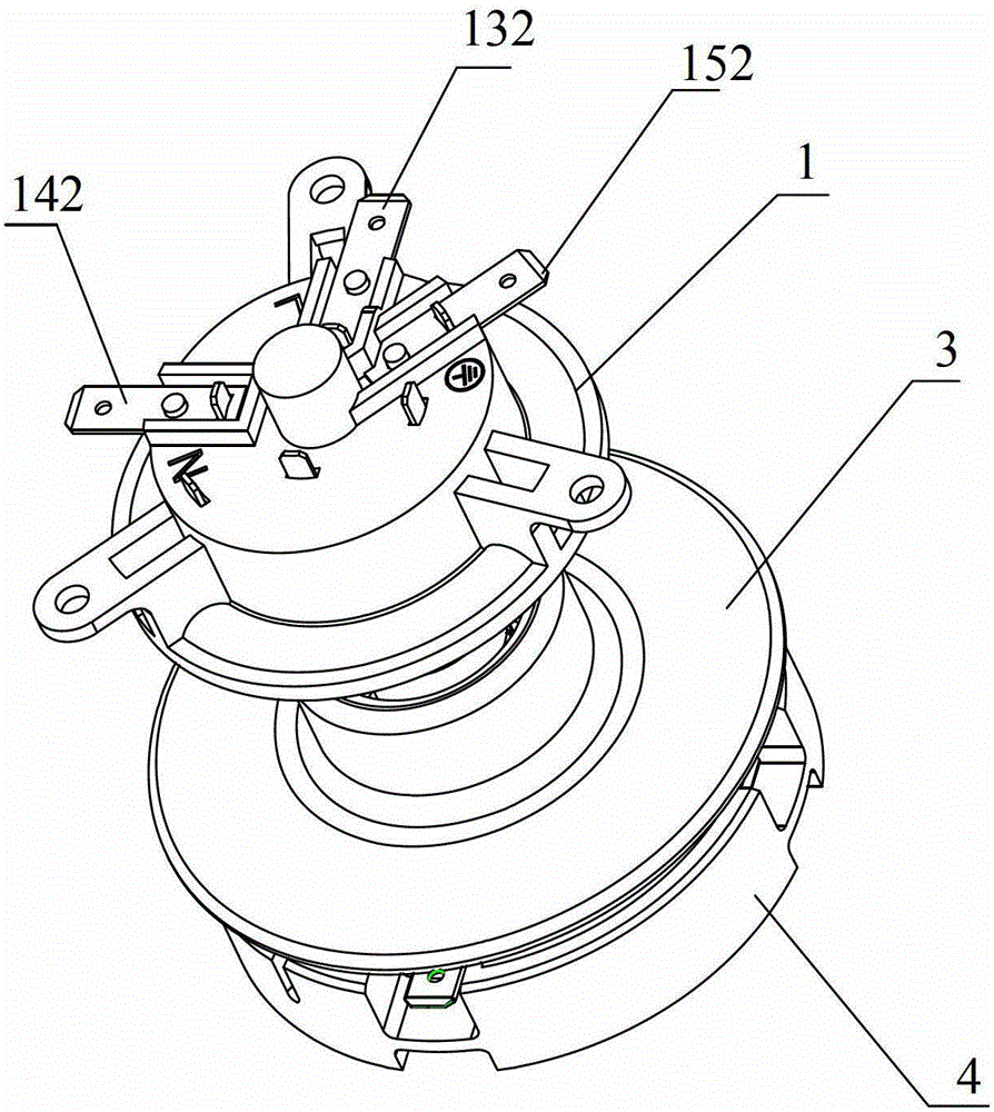
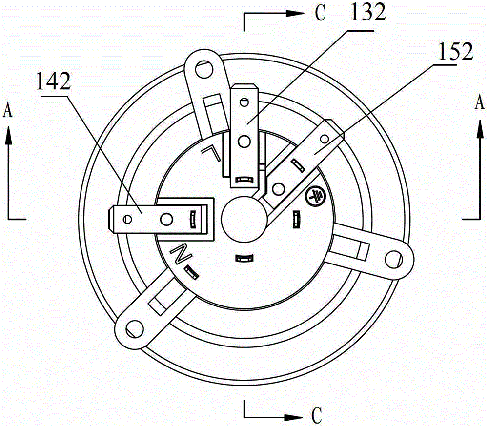
[0079] Embodiment 1, Figure 1~Figure 5 In combination, a coupler for electrical appliances is provided, including an input socket assembly 1 , an output plug assembly 3 and a waterproof cover 4 .

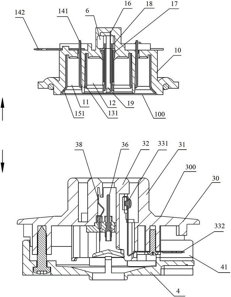
[0080] The input socket assembly 1 includes an input socket body 10 , on the upper surface of the input socket body 10 are provided an input L line insert 132 , an input N line insert 142 and an input ground line insert 152 .

[0081] The lower surface 100 of the input socket body 10 is dug with a large circular groove 11, a middle circular groove 12, and a small circular groove 19 whose axes coincide with each other, and the small circular groove 19 is set in the middle circular groove. In the groove 12, the middle ring groove 12 is sleeved in the big ring groove 11.

[0082] The ring-shaped input ground wire contact 151 is set on the outer surface of the large ring groove 11, and the ring-shaped input N line contact 141 is set on the inner ring surface of the big ring groove 11....

Embodiment 2

[0106] Embodiment 2. In Embodiment 1, the container attribute identification input terminal 17 and the container attribute identification output terminal 37 are cancelled, and the rest is the same as Embodiment 1.

[0107] In actual use, an electrical appliance type button is provided on the base panel, that is, the control panel is informed of the type of electrical appliance currently used through the button on the panel. All the other work contents are equal to embodiment 1.

Embodiment 3

[0108] Embodiment 3 is in an existing coupler (such as Figure 6-1~Figure 6-5 As shown), the main changes are the following two points:

[0109] 1. Change the relative position height of output ground contact 351, input ground contact 151, output L line contact 331, input L line contact 131, output N line contact 341, and input N line contact 141. It can also be realized that when the input socket assembly 1 and the output plug assembly 3 are coupled, the output ground contact 351 contacts the input ground contact 151 first, and then the phase between the output L line contact 331 and the input L line contact 131 The contacting and phase contacting of the output N-wire contact 341 and the input N-wire contact 141 are performed simultaneously.

[0110] 2. Set the container attribute identification input end 17 and the identification element 6 on one of the bases, and the identification element 6 is electrically connected to the container attribute identification input end 17 a...


PUM


Abstract

The invention discloses an electric appliance coupler with an identity identification function. The electric appliance coupler comprises an input socket component (1) and an output plug component (3), wherein the input socket component (1) comprises an input socket base body (10); a strong current input component, a weak current control input end component and an identification element (6) are arranged on the input socket base body (10); the output plug component (3) comprises an output plug base body (30); a strong current output component and a weak current control output end component are arranged on the output plug base body (30); and when the input socket component (1) and the output plug component (3) are coupled, a weak current common input end (16) and a weak current common output end (36) are contacted, and / or a container attribute identification input end (17) and a container attribute identification output end (37) are contacted after the strong current input component and the strong current output component are contacted.

Description

technical field [0001] The invention relates to a coupler for electrical appliances. Background technique [0002] Specialization and intelligence are the development trend of small household appliances at present. For example, electric kettles with automatic heat preservation; intelligent electric steamers, rice cookers, and induction cookers; special electric egg cookers, electric yogurt machines, constant temperature baby bottles and baby bottle sterilizers; automatic quantitative electric decoction devices, etc. Each of the above-mentioned small appliances has a corresponding controller, especially intelligent control appliances. Each appliance has a set of electronic control boards, and the circuit design of these electronic control boards is basically the same, and their functions are nothing more than controlling the cooking time. , cooking power and holding temperature. In daily life, in order to improve the quality of life, users often purchase the above-mentioned...

Claims


Application Information

Patent Timeline
Patent Type & Authority Patents(China)
IPC IPC(8): H01R13/66H01R13/70
Inventor 董晓波
Owner 董晓波
Why Eureka
Try Eureka