Production method of polyurethane spray product with hole

A production method, polyurethane technology, applied in the production field of polyurethane spray products, to achieve the effect of simple operation, low development cost, and high-efficiency production

Active Publication Date: 2013-01-30
YANTAI ZHENGHAI HIGH TECH
View PDF6 Cites 0 Cited by
  • Summary
  • Abstract
  • Description
  • Claims
  • Application Information

AI Technical Summary

Problems solved by technology

[0006] The purpose of the present invention is to overcome above-mentioned deficiencies in the prior art, and provide a kind of production method of the polyurethane spraying product with small hole, mainly solve existing technology needs to develop punching mold separately, carry out punching operation, or need to clean up one by one overflow pit problem

Method used


Image

  • Production method of polyurethane spray product with hole
  • Production method of polyurethane spray product with hole

Examples


Embodiment 1

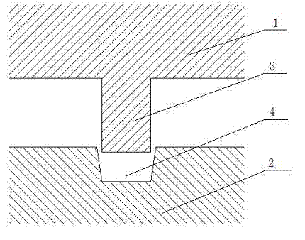
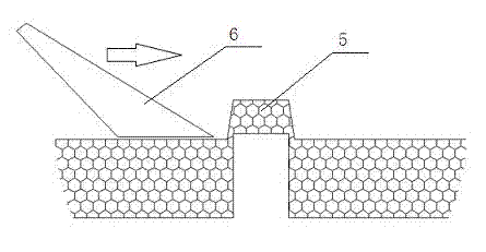
[0014] Embodiment 1, the product is an example with a glass fiber reinforced polyurethane material with a honeycomb paper sandwich, a product thickness of 10mm, and several small holes with a diameter of 5mm on the product; see figure 1 , 2 , the forming mold is a punch 1 on one side and a die 2 on one side. The punch 1 has a boss 3 with a diameter of 5 mm and a height of 11 mm; the die 2 has a pit 4 with a depth of 3 mm, and the diameter of the pit mouth is 6 mm. The diameter of the bottom of the pit is 5 mm; when the mold is closed, the boss 3 on the punch 1 falls into the pit 4 on the die 2, and there is a gap between the boss 3 and the pit 4; The product, the scrap 5 in the pit can be cut 6 with a flat knife with a width of 6~10mm.

Embodiment 2

[0015] Embodiment 2, the product is a natural fiber reinforced polyurethane material with a honeycomb paper sandwich, and the product thickness is 8mm, with several small holes with a diameter of 5mm on the product; see figure 1 , 2 , the forming mold is a punch 1 on one side and a die 2 on one side; the punch 1 has a boss 3 with a diameter of 5 mm and a height of 10 mm; the die 2 has a pit 4 with a depth of 4 mm, and the diameter of the pit mouth is 6 mm. The diameter of the bottom of the pit is 5.5 mm; when the mold is closed, the boss 3 on the punch 1 falls into the pit 4 on the die 2, and there is a gap between the boss 3 and the pit 4; after molding For the product, the waste material 5 in the pit can be cut off with a flat knife 6 with a width of 6-10mm.

Embodiment 3

[0016] Embodiment 3, the product is a glass fiber reinforced polyurethane material with a honeycomb paper sandwich, and the product thickness is 12mm, with several small holes with a diameter of 8mm on the product; see figure 1 , 2 , the forming mold is a punch 1 on one side and a die 2 on one side; the punch 1 has a boss 3 with a diameter of 8 mm and a height of 14 mm; the die 2 has a pit 4 with a depth of 4 mm, and the diameter of the pit mouth is 14 mm. The diameter of the bottom of the pit is 12 mm; when the mold is closed, the boss 3 on the punch 1 falls into the pit 4 on the die 2, and there is a gap between the boss 3 and the pit 4; Product, the waste material 5 in the pit can be cut off with the flat knife 6 of width 6~10mm.


PUM


Abstract

The invention discloses a production method of a polyurethane spray product with a hole, comprising the following steps: making one surface of a formed mold into a punch, arranging a boss with corresponding shape of the hole at the position of the hole, making the other surface of the formed mold into a concave mold to form a concave pit with a diameter being larger than the diameter of the hole at the corresponding position of the hole; when the mold is closed, letting the boss of the punch fall into the concave pit of the concave mold; after a product is formed, using a knife to cut off the boss formed at the concave pit position of the mold along with the plane. According to the invention, the problem that waste material sticked in an overflow pit leads to frequent cleaning is avoided; there is no need for making a punching mold; after forming, the hole that meets the needs can be obtained by only using the knife to simply clean the waste material, thus high efficiency production can be realized with low development cost.

Description

Technical field: [0001] The invention relates to the technical field of production of polyurethane products, in particular to a production method of polyurethane sprayed products with small holes. Background technique: [0002] Polyurethane products reach the spraying production process, which refers to the use of glass fiber felt or natural fiber felt as the reinforcement material, or a sandwich material can be set between two layers of glass fiber felt, and the surface of the reinforcement material is sprayed with polyurethane foam material and put into the mold Foam molding, a process for producing products with a certain strength. [0003] Products produced by the spraying process generally adopt the die-cutting process or the extrusion-cutting process. [0004] The mold adopts the punching process, one side is made into a punch with a boss corresponding to the shape of the small hole, and the other side is made into a flat die, the height of the boss is slightly sm...

Claims


Application Information

Patent Timeline
Patent Type & Authority Applications(China)
IPC IPC(8): B29C70/30B29C33/00
Inventor 李海帆朱维珍李光福张宁杜迎梅
Owner YANTAI ZHENGHAI HIGH TECH
Why Eureka
Try Eureka