Optical power microwave testing device and method based on dye optical sensitization characteristics

A microwave measurement and optical power technology, applied in the field of microwave photonics, can solve the problems of processing cost and generality of use, limited use conditions and application scope, and decreased optical power detection accuracy, and achieves a wide range of power distribution and variation. Small, responsive effects

Inactive Publication Date: 2018-11-13
UNIV OF ELECTRONICS SCI & TECH OF CHINA
View PDF6 Cites 2 Cited by
  • Summary
  • Abstract
  • Description
  • Claims
  • Application Information

AI Technical Summary

Problems solved by technology

The logarithmic amplifier has a larger range, generally its value can reach 60dB, and it has a relatively uniform range in the entire range, but due to the existing technology, the resolution in the range is too low, resulting in low optical power detection accuracy. drop with it
The sampling range of the optical power of the traditional AD converter is generally within 0~20dBm, but the actual optical power is usually higher than 20dBm, at this time, the traditional AD converter will no longer meet the requirements
In addition, some integrated optical power detection devices can also realize the simple detection of optical radiation power, but due to the limitation of processing cost and universality of use, it cannot be widely used.
[0004] To sum up, the detection amplitude range of traditional optical power detection technology is small, and technology and cost limit its use conditions and application range

Method used


Image

  • Optical power microwave testing device and method based on dye optical sensitization characteristics
  • Optical power microwave testing device and method based on dye optical sensitization characteristics
  • Optical power microwave testing device and method based on dye optical sensitization characteristics

Examples


Embodiment Construction

[0035] Embodiments of the present invention are described below through specific examples, and those skilled in the art can easily understand other advantages and effects of the present invention from the content disclosed in this specification.

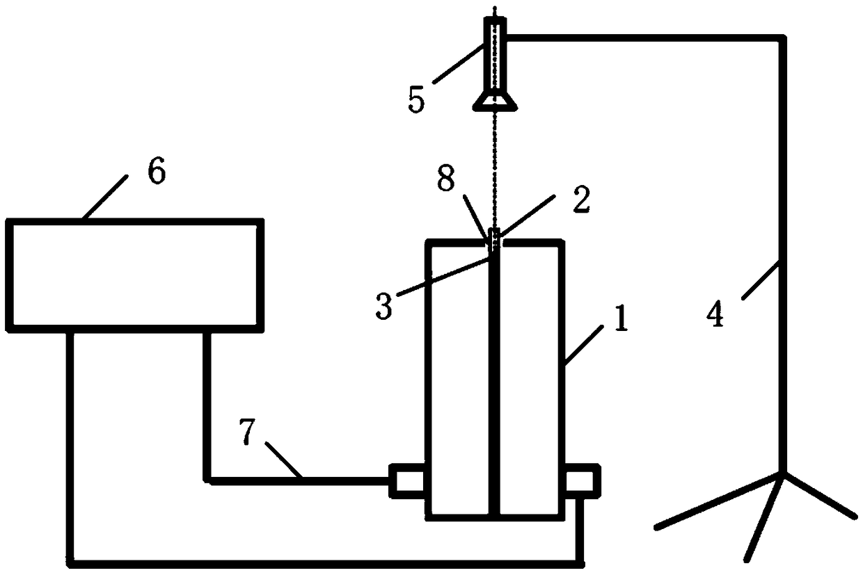
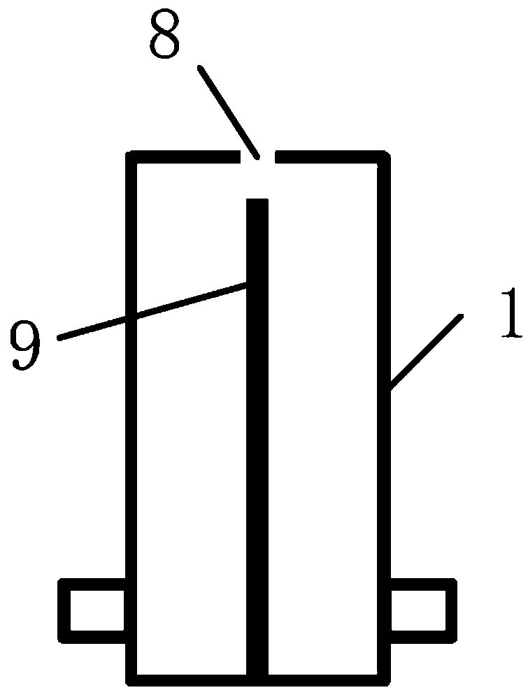
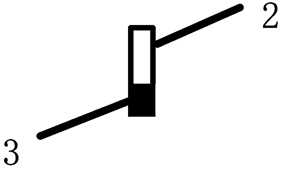
[0036] like figure 1 As shown, the optical power microwave test device based on the optical sensitization characteristics of the dye, including the coaxial resonant cavity 1, the optical fiber 2, the light source fixing bracket 4, the light source 5 and the vector network analysis instrument 6, the optical fiber 2 is vertically inserted into the coaxial resonator test hole 8; the bottom surface of the optical fiber 2 is coated with an optical sensitizing dye 3; the light source 5 is fixed by the light source fixing bracket 4, and vertically The test hole 8 of the coaxial resonant cavity is irradiated; the vector network analyzer 6 is connected with the coaxial resonant cavity 1 through a microwave cable 7 .

[0037] The working freq...


PUM


Abstract

The invention provides an optical power microwave testing device and method based on dye optical sensitization characteristics. The device comprises a coaxial resonant cavity, an optical fiber, an optical sensitization dye, a light source, a light source fixing bracket and a vector network analyzer, wherein the vector network analyzer is connected with the coaxial resonant cavity through a microwave cable; the surface of the optical fiber is coated with the optical sensitization dye, and the end, coated with the dye, of the optical fiber is vertically placed in a test hole of the coaxial resonant cavity; the light source is fixed by the bracket and vertically irradiates the test hole of the coaxial resonant cavity. The device has the characteristics of high test precision, good test stability, low use and maintenance cost and low requirements for sample placement; besides, the optical sensitization dye is adopted, wide spectrum detection from red light to purple light can be achieved;the coaxial resonant cavity with concentrated field strength and high quality factor is adopted, and real-time response to the instantaneous change of the radiation power of the light source can be achieved in the test process, so that accuracy of test results is ensured.

Description

technical field [0001] The invention belongs to the technical field of microwave photonics, and in particular relates to an optical power testing device and method. Background technique [0002] With the rapid development of optical communication technology and passive optical fiber network technology, optical power detection is particularly important. Changes in optical power can easily lead to communication and network failures. In the field of optical communication, in order to ensure the continuity, stability and safety of the work between devices, all optical devices are usually tested. [0003] At present, the main method of optical power detection is AD conversion, which couples the light to be measured to APD (avalanche photon detector, avalanche photodiode) or PIN tube through a coupler, and then amplifies the obtained voltage through an amplifier, and Sampling is carried out, and finally the optical power value to be detected can be calculated. Commonly used ampl...

Claims


Application Information

Patent Timeline
Patent Type & Authority Applications(China)
IPC IPC(8): G01M11/00
Inventor 李亚峰余承勇高冲龙嘉威李恩张云鹏高勇杨涛
Owner UNIV OF ELECTRONICS SCI & TECH OF CHINA
Why Eureka
Try Eureka