Multi-station stamping processing equipment and turnover mechanism thereof

A technology of stamping processing and turning mechanism, which is applied in the direction of metal processing equipment, forging/pressing/hammering machinery, manufacturing tools, etc. It can solve the problems of low workpiece processing efficiency, workpiece inability to turn over, and workpiece turning over, so as to achieve convenient design and processing, Simple structure and improved reliability

Active Publication Date: 2021-02-02
河南航天精工制造有限公司
View PDF6 Cites 2 Cited by
  • Summary
  • Abstract
  • Description
  • Claims
  • Application Information

AI Technical Summary

Problems solved by technology

[0006] The purpose of the present invention is to provide a turning mechanism for multi-station stamping processing equipment to solve the technical problem in the prior art that the workpiece processing efficiency is low because the workpiece cannot be turned over on the stamping processing equipment; the purpose of the present invention is also to provide A multi-station stamping processing equipment to solve the technical problem of low workpiece processing efficiency in the prior art because the workpiece cannot be turned over on the stamping processing equipment

Method used


Image

  • Multi-station stamping processing equipment and turnover mechanism thereof
  • Multi-station stamping processing equipment and turnover mechanism thereof
  • Multi-station stamping processing equipment and turnover mechanism thereof

Examples


specific Embodiment 1

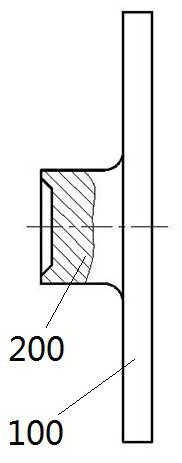
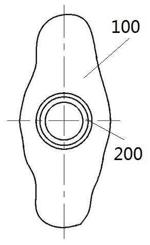
[0097] Taking the turning mechanism installed on a multi-station cold heading machine as an example, the turning mechanism for multi-station stamping processing equipment of the present invention is introduced in detail. Such as Figure 5 and Figure 6 As shown, the turning mechanism includes a die 1 and a punch 2. The die 1 includes a die body 10, a slider 11, a bar body 12 and an ejector 13. The die body 10 is used to be installed in the die body of a cold heading machine. cavity, such as Figure 7 and Figure 8 As shown, the die body 10 is provided with an overturn cavity 101, a guide hole 102, an avoidance hole 103 and a step hole 104. The overturn cavity 101 runs through the die body 10 along the left and right directions. The ejector 13 can move left and right and is assembled on the right side of the turning cavity 101; the guide hole 102 extends along the left and right directions, and the slider 11 is guided and slidably assembled in the guide hole 102; into the s...

specific Embodiment 2

[0112] The difference between it and the above-mentioned embodiment 1 mainly lies in that in the above-mentioned embodiment 1, a stopper rod body is provided on the die body, and a pusher is provided on the punch body, and the pusher pushes the lower part of the stopper rod body into the turning cavity The stamping parts to be stamped are stopped by the lower part of the stop rod body, so as to avoid the obstruction of the turning process of the stamping parts to be stamped. In this embodiment, there is no stop rod body on the die body, and no pusher on the punch body. At this time, by improving the machining accuracy of the turning cavity and setting the size of the turning cavity reasonably, the turning process of the stamped parts can be avoided. blocked by the flip chamber.

specific Embodiment 3

[0114] The difference between it and the above-mentioned embodiment 1 mainly lies in that in the above-mentioned embodiment 1, sliders are installed on the left and right guiding activities of the concave mold body, and the pusher pushes the slider, and pushes the stop rod body through the slider. In this embodiment, no slide block is assembled on the die body, and a matching inclined surface is directly arranged on the head of the stop rod, and the pusher is used to push the matching inclined surface, so that the stop rod body moves downward. Of course, in other embodiments, a matching slope can also be provided at the left end of the push piece, so that the stop rod body moves downward when the push piece pushes the stop rod body.


PUM


Abstract

The invention relates to multi-station stamping processing equipment and a turnover mechanism thereof. The turnover mechanism comprises a concave mold body and a convex mold body, wherein a turnover cavity for turning over a part to be stamped by virtue of self-gravity is arranged on the concave mold body; the turnover cavity is through horizontally, the left end of the turnover cavity is used forintroducing the part to be stamped, and the right end of the turnover cavity is used for allowing a jacking mechanism of the stamping processing equipment to jack the turned-over part to be stamped;an inserting space is formed in the convex mold body; while the inserting space moves rightwards in the convex mold body, the part to be stamped is inserted from the horizontal state, and is pushed into the turnover cavity; a feeding rod body can be arranged in the inserting space and can be rightwards jacked by a hitting mechanism of the stamping processing equipment; the part to be stamped is separated from the inserting space and is only supported by a wall surface of the turnover cavity; the right side of the turnover cavity is equipped with an ejecting part for leftwards ejecting an ejecting mechanism of the stamping processing equipment; the turned-over part to be stamped is jacked out of the turnover cavity from the vertical state, so that turnover of the part to be stamped is realized, and thus, continuous processing, on the stamping processing equipment, of workpieces is realized.

Description

technical field [0001] The invention relates to a multi-station stamping processing equipment and a turning mechanism thereof. Background technique [0002] Most of the multi-station cold heading machines, warm heading machines and hot heading machines in the prior art are processed in the horizontal direction, that is, the stamping process or workpiece transfer of the workpiece can only be carried out in the horizontal direction, and the workpiece cannot be processed in the vertical direction. Flipping, that is, it is impossible to change the workpiece from the horizontal direction to the vertical direction. Therefore, for workpieces with complex shapes and structures that need to be stamped in both the horizontal and vertical directions of the workpiece, the above-mentioned multi-station Stamping processing equipment realizes continuous processing. [0003] For example, for the pallet nut disclosed in the utility model patent whose authorized notification number is CN2114...

Claims


Application Information

Patent Timeline
Patent Type & Authority Applications(China)
IPC IPC(8): B21J13/02B21J13/12B21J13/14B21J5/08
CPCB21J13/02B21J13/12B21J13/14B21J5/08
Inventor 赵文龙余军伟许吉星历虎高程付建建高乾军李宝磊郑鹏辉刘霖杨冬梅邵阳
Owner 河南航天精工制造有限公司
Why Eureka
Try Eureka