Restraint device for column fire resisting test

A technology of restraint device and restraint beam, which is applied in the direction of measuring device, machine/structural component test, instrument, etc., can solve the problems of test device damage, temperature stress, inaccurate test results, etc., to provide in-plane rigidity, improve Safety factor, effect of improving flexibility

Active Publication Date: 2013-01-30
NINGBO UNIV
View PDF3 Cites 8 Cited by
  • Summary
  • Abstract
  • Description
  • Claims
  • Application Information

AI Technical Summary

Problems solved by technology

However, most of the current research is mainly on independent components, and there are mainly shortcomings in the following aspects: in the experiment, the independent components can freely expand and deform during the heating process, and are not constrained by the surrounding components, so that no temperature stress is generated. In the actual building, the expansion and deformation of the column is constrained by the surrounding components, resulting in temperature stress
[0004] By connecting different support forms at both ends of the column, it is possible to study the fire resistance and damage mode of the columns subject to different constraints in the fire, and measure the expansion deformation of the column in the fire and the expansion force generated by the restriction of the expansion deformation. , but the device has the following defects: (1) The device occupies a large area and cannot be flexibly adjusted in size; (2) The protection factor is not considered, and when the load is greater than the maximum load that the test device can bear, the test device produces (3) Since the restraint beam and the two restraint rods are located on the same plane, the device cannot provide out-of-plane stiffness, and cannot realize the test research under the action of eccentric load, resulting in the test results Inaccurate

Method used


Image

  • Restraint device for column fire resisting test
  • Restraint device for column fire resisting test
  • Restraint device for column fire resisting test

Examples


specific Embodiment

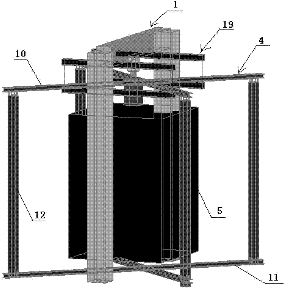
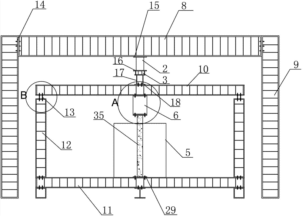
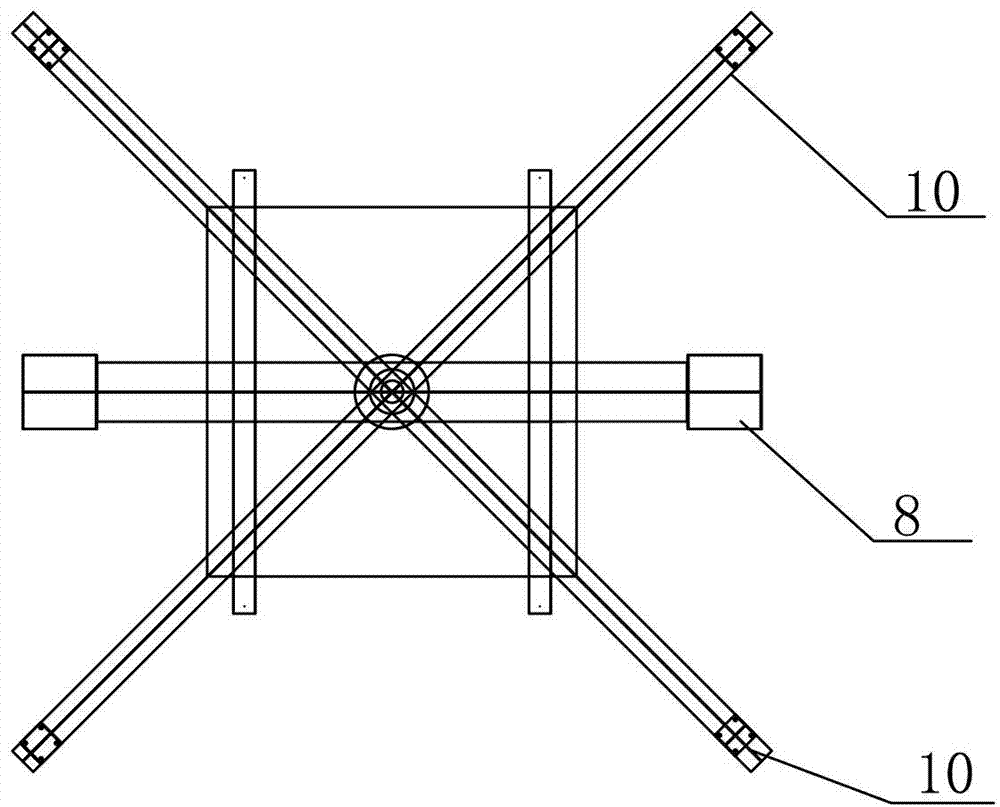
[0031] The present invention is a restraint device for column fire resistance test, such as figure 1 and figure 2 As shown, it includes a loading reaction frame 1, a jack 2, a load sensor 3, a constraint frame 4, a heating furnace 5, a measuring column generating a constraint force device 6, and several displacement gauges 7 (see Figure 4 shown), the loading reaction frame 1 is mainly surrounded by a steel beam 8 arranged horizontally and two steel columns 9 arranged vertically. not shown in ) fixedly connected rectangular frame, the rectangular frame includes a horizontally arranged upper restraint beam 10, a lower restraint beam 11 and two vertically arranged restraint columns 12, the upper restraint beam 10 is located at the lower end of the steel beam 8, the jack 2 and the load sensor 3. Arranged sequentially from top to bottom between the steel beam 8 and the upper constraining beam 10. The measuring column generating constraining force device 6 and the heating furnace...


PUM


Abstract

The invention discloses a restraint device for a column fire resisting test. The device comprises a loading counter-force rack, a lifting jack, a load sensor, a restraint framework, a heating stove, a measured column generating constraint force device and a plurality of displacement meters. The device is characterized in that the restraint framework includes two rectangular frameworks which are mutually crossed and fixedly connected through a bolt pair, each rectangular framework comprises an upper restrained beam, a lower restrained beam and a restrained column, the upper and lower restrained beams are horizontally arranged, the upper restrained beams are located at the lower end of a steel beam, the lifting jack and the load sensor are sequentially disposed between the steel beam and the upper restrained beams, the measured column generating constraint force device and the heating stove are sequentially mounted between the upper restrained beams and the lower restrained beams, a testing column is mounted in the heating stove, the upper end of the testing column penetrates through the heating stove to be connected with the measured column generating constraint force device, and the lower end of the testing column penetrates through the heating stove to be connected with the lower restrained beams. The restraint device for the column fire resisting test has the advantages that the floor space is small, the manufacture is easy, the usage is convenient and flexible, the operability is high, the device is safe and reliable, simultaneously the stiffness out of plane can be effectively provided, and the experimental study can be achieved under the action of eccentric loading.

Description

technical field [0001] The present invention relates to a restraint device for column fire resistance test. Background technique [0002] The column is an important vertical load-bearing member in the building structure, which bears and reliably transmits the vertical load. When the building encounters a fire, the fire resistance of the column will play a vital role in the overall safety of the structure. The fire resistance of the load-bearing column The limit has a decisive influence on the collapse resistance of the building structure as a whole. Therefore, it is of great significance to study the mechanical performance of the column under fire and propose a reasonable fire-resistant design method to ensure the performance and overall safety of the structure under fire. In actual structures, columns are inevitably connected with frame beams, floor slabs and other components, and become de facto constraint components. Due to the existence of axial constraints and lateral...

Claims


Application Information

Patent Timeline
Patent Type & Authority Applications(China)
IPC IPC(8): G01M99/00
Inventor 李俊华钱钦
Owner NINGBO UNIV
Why Eureka
Try Eureka