Multi-frequency-point satellite navigation terminal antenna

A technology of satellite navigation and terminal antenna, which is applied in the directions of antenna grounding device, independent antenna unit combination, antenna support/installation device, etc. It can solve the problems of unseen high frequency and wide beam, and achieve easy impedance matching and reliability The effect of high and extended bandwidth

Active Publication Date: 2015-02-11
SPACE STAR TECH CO LTD
View PDF8 Cites 0 Cited by
  • Summary
  • Abstract
  • Description
  • Claims
  • Application Information

AI Technical Summary

Problems solved by technology

These antennas give the design of satellite navigation antennas with broadband or dual frequency points, but the frequencies are all concentrated in the range of 1.15-1.65GHz, and no higher frequencies are involved
[0005] After searching, there is no relevant literature report about satellite navigation terminal antenna with high frequency and wide beam, which can be used for various navigation terminals

Method used


Image

  • Multi-frequency-point satellite navigation terminal antenna
  • Multi-frequency-point satellite navigation terminal antenna

Examples


Embodiment Construction

[0019] The technical solution of the present invention will be described in detail below in conjunction with the accompanying drawings.

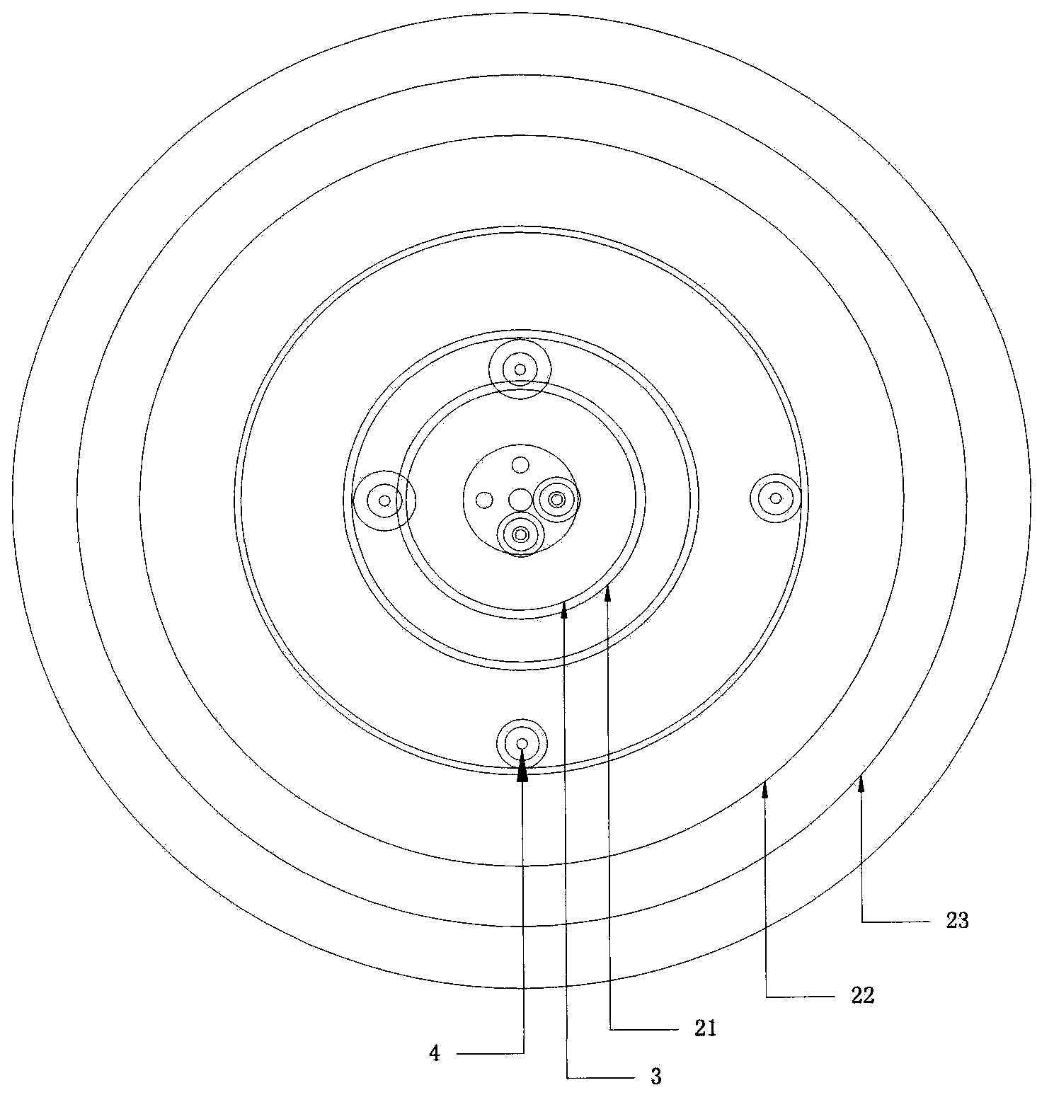
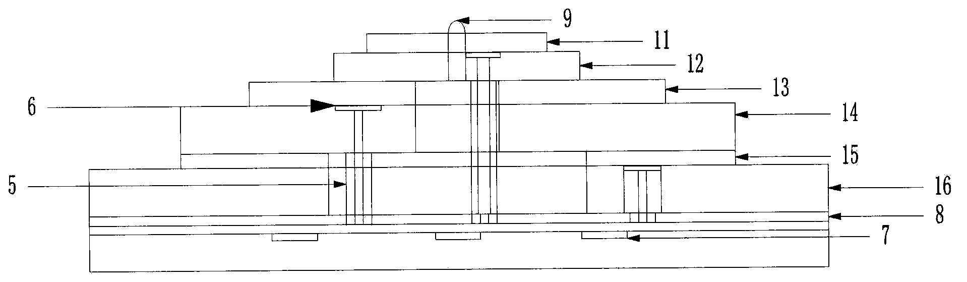
[0020] Such as figure 1 , 2 As shown, a multi-frequency point satellite navigation terminal antenna of the present invention includes six layers of microwave dielectric substrates, three metal radiation sheets, one parasitic patch 3, six T-shaped metal columns 4, six dielectric columns 5, Six dielectric spacers 6, three 3dB bridges 7, one floor 8 and one set screw 9.

[0021] Six layers of microwave dielectric substrates are stacked sequentially from top to bottom, the first layer of microwave dielectric substrate 11 is located on the top layer; the second layer of microwave dielectric substrate 12 and the third layer of microwave dielectric substrate 13 are high-end frequency radiation layers, that is, covering 2441 to 2541MHz range; the fourth layer of microwave dielectric substrate 14 and the fifth layer of microwave dielectric substrat...


PUM


Abstract

The invention discloses a multi-frequency-point satellite navigation terminal antenna which is applicable to a plurality of navigation terminal systems. The multi-frequency-point satellite navigation terminal antenna comprises six layers of microwave dielectric substrates, three metal irradiating sheets, a parasitic sticking plate, six T type metal columns, six dielectric columns, six dielectric washers, three 3dB bridges, a floor and a positioning bolt; the six layers of microwave dielectric substrates are sequentially overlapped from top to bottom; the parasitic sticking sheet is fixed on the first layer of microwave dielectric substrate; every two T type metal columns 4 are arranged as a group for performing feed to one metal irradiating sheet. According to the multi-frequency-point satellite navigation terminal antenna, the antenna with overlapping structure is adopted, so that the working frequency of the antenna can reach higher frequency range, and four modes, namely GPS (Global Position System) mode, GALILEO mode, GLONASS (Global Navigation Satellite System) mode and Beidou mode, can be covered; and meanwhile, the capacitive coupling feed mode is carried out on the radiating sheets, so that the bandwidth is effectively increased.

Description

technical field [0001] The invention relates to the technical field of antennas, in particular to a multi-frequency point satellite navigation terminal antenna that can be applied to various navigation terminal systems. Background technique [0002] In order to solve the problems of single system coverage gap and low navigation accuracy, multi-mode collaborative work has become a trend in the future satellite navigation system. The multi-mode satellite navigation terminal antenna is required to be able to cover the four modes of GPS, GALILEO, GLONASS and Beidou. The working frequency band of the antenna should meet the broadband requirements of 1164-2491MHz. The radiation direction characteristic is characterized by wide beam and the polarization mode is right-handed. circular polarization. [0003] At present, most of the multi-frequency satellite navigation terminal antennas widely used at home and abroad adopt a stacked structure to realize broadband operation, and the f...

Claims


Application Information

Patent Timeline
Patent Type & Authority Patents(China)
IPC IPC(8): H01Q21/30H01Q1/36H01Q1/38H01Q1/50H01Q1/48H01Q1/12
Inventor 韩琳郭文嘉李新华
Owner SPACE STAR TECH CO LTD
Why Eureka
Try Eureka