Plunger press and method for producing compressed bales

A press and plunger type technology, which is applied in the field of plunger presses, can solve the problems of stress, twisting and material damage of unideal materials, and achieve uniform packing density, high packing density, and high packing density. Effect

Active Publication Date: 2013-01-30
KUHN GELDROP
View PDF8 Cites 5 Cited by
  • Summary
  • Abstract
  • Description
  • Claims
  • Application Information

AI Technical Summary

Problems solved by technology

This leads to undesirably highly twisted material stresses and a great risk of twisted material breakage

Method used


Image

  • Plunger press and method for producing compressed bales
  • Plunger press and method for producing compressed bales
  • Plunger press and method for producing compressed bales

Examples


Embodiment Construction

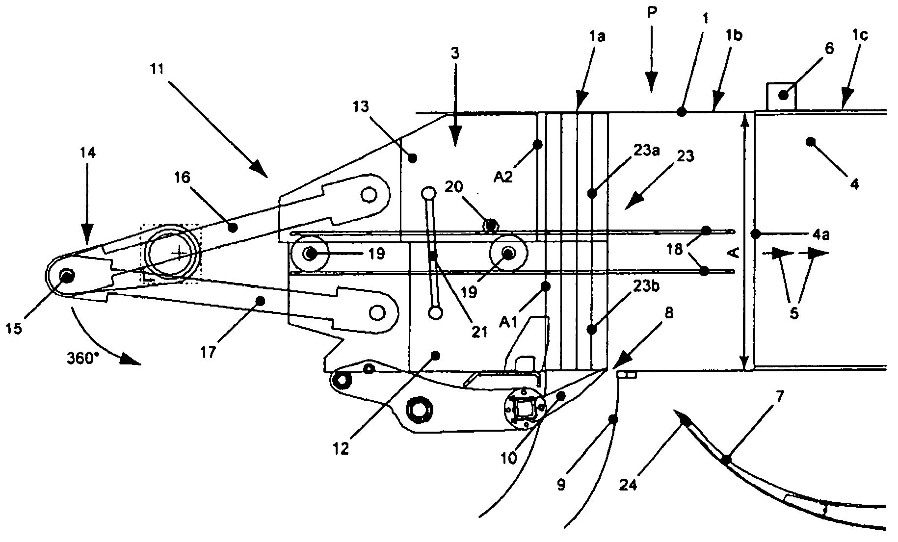
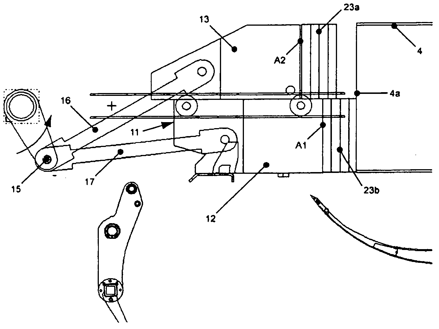
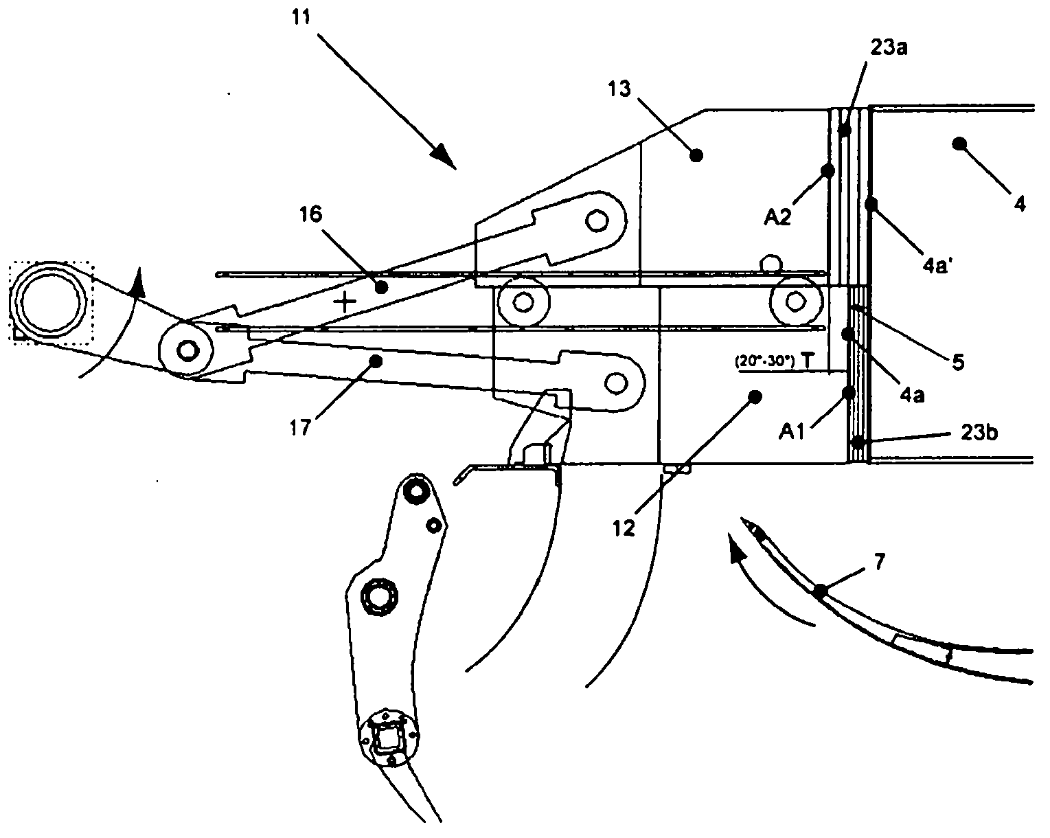
[0039] Figures 1 to 4 Shown is the production of compressed bales for agricultural and / or industrial use (e.g. hay, straw, biomass or fibrous bodies) in a ram press as part of an open channel baler (not shown). different stages of operation. As is conventional, the ram press P has a frame (not shown) enclosing the baler housing 1, which is arranged on a movable undercarriage, which is either self-propelled, or coupled via The tongue part of the coupling device is pulled. The plunger press P is either equipped with its own drive source, such as an internal combustion engine, or is supplied, for example, with hydraulic power from a traction vehicle. Alternatively, the ram press P can be integrated in the box baler.

[0040] The feed duct 9 is connected to the baler housing 1 , in particular to the underside (inlet 8 ) of the feed supply part 1 a , which in the baler housing 1 passes through the compression part 1 b and the strand channel part 1 c and continue until figure ...


PUM


Abstract

In a plunger press (P) for producing compressed bales, the plunger press (P) comprising a bale case (1) accommodating a linearly reciprocating plunger structure (11), a material feeding duct (9) laterally leading into the bale case (1), and a plunger structure crank mechanism (14) driven by a drive source, the plunger structure (11) compressing a respective material charges (23) fed into the bale case (1) against a material strand (4) of at least one already compressed material charge, and linearly stepwise shifting the compressed material strand (4) in the bale case by overcoming a back pressure of the material strand, the plunger structure (11) having at least two structurally separated compression surfaces (A1, A2) each being smaller than a cross-section area (A) of the bale case (1), the compression surfaces (A1, A2); being parallelly driven in the linear reciprocation direction and relative to each other with a time shift (T). According to a method for producing compressed bales a material strand (4) forming the compressed bale is compressed alternatingly on partial surfaces of the cross-section area (A) with a respective time shift (T) between compression cycles.

Description

technical field [0001] The invention relates to a plunger press according to the preamble of claim 1 and a method according to the preamble of claim 15 . Background technique [0002] The plunger press of US 4,034,543 is an example of prior art and comprises a one-piece plunger structure whose active pressing surface corresponds to the cross-sectional area of ​​the baler housing or the materials stocks. The plunger arrangement feeds material against the end face of the strand during each compression cycle. Feed material is fed laterally from the material delivery conduit into the baler housing while the plunger structure is retracted against the end face of the material strand. The plunger structure is coupled via two crank rods to a crankshaft driven by a clutch from a drive source including a flywheel. The feed material is fed into the baler housing by a pivotable feed blade so that the feed material has been pre-compressed between the plunger structure and the material...

Claims


Application Information

Patent Timeline
Patent Type & Authority Applications(China)
IPC IPC(8): A01F15/04B30B9/30
CPCB30B9/3021A01F15/042
Inventor M・范德拉尔斯霍特M・J・旺德盖姆
Owner KUHN GELDROP
Why Eureka
Try Eureka