Multi-way valve
A technology of multi-way valves and valve sliders, which is applied in the direction of multi-way valves, valve devices, servo meter circuits, etc., to achieve the effect of reducing friction and wear
- Summary
- Abstract
- Description
- Claims
- Application Information
AI Technical Summary
Problems solved by technology
Method used
Image

Examples
Embodiment Construction
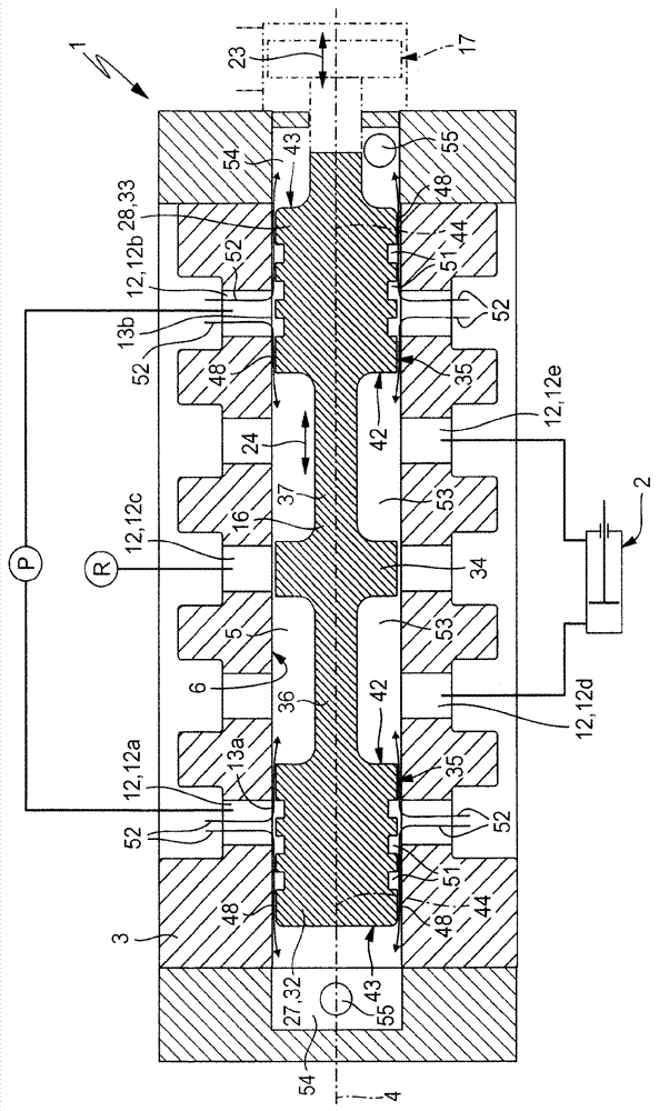
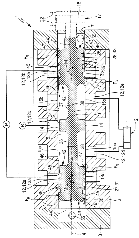
[0026] The multi-way valve 1 as can be seen in the drawings can be used to control any type of fluid flow. A typical application is the control of the flow of pressurized fluid to and from a load 2 indicated schematically in the figure, such as a fluid-operated drive.
[0027] Usually, the controlled pressure fluid is compressed air or pressure oil. However, other fluid media can also be controlled.
[0028]The multi-way valve 1 of this embodiment is designed as a three-position five-way valve. However, the invention can also be implemented in valves with other functionalities.
[0029] The multi-way valve 1 has a valve housing 3 in which is located an elongated control chamber 5 with a longitudinal axis 4 . Expediently, the control chamber 5 has a circular, preferably annular, cross section. On the peripheral side, the control chamber 5 is delimited by a wall referred to as the peripheral wall 6 , which is formed directly by the valve housing 3 in the exemplary embodiment...
PUM
 Abstract
Description
Claims
Application Information
 - R&D
- Intellectual Property
- Life Sciences
- Materials
- Tech Scout
- Unparalleled Data Quality
- Higher Quality Content
- 60% Fewer Hallucinations
Browse by: Latest US Patents, China's latest patents, Technical Efficacy Thesaurus, Application Domain, Technology Topic, Popular Technical Reports.
© 2025 PatSnap. All rights reserved.Legal|Privacy policy|Modern Slavery Act Transparency Statement|Sitemap|About US| Contact US: help@patsnap.com