Sealed rotary joint for turret rotator

a rotary joint and turret technology, applied in the direction of electrostatic holding devices, machines/engines, machine supports, etc., can solve the problems of contaminate penetration failure of users problems such as damage to land and sea based camera systems, and problems such as the use of upward facing turrets and ball assemblies

Active Publication Date: 2006-02-16
TELEDYNE FLIR LLC
View PDF7 Cites 21 Cited by
  • Summary
  • Abstract
  • Description
  • Claims
  • Application Information

AI Technical Summary

Benefits of technology

[0010] As a second element for sealing the clearance gap, a wiper seal is positioned in the clearance gap for closing the clearance gap. The wiper seal comprises a fixed annular seal surface attached to the fixed element and an annular flexible seal element attached to the rotatable element. The wiper seal annular flexible seal element is forced into contact with the fixed annular seal surface by a bending force generated by an interference contact between the annular flexible seal element and the fixed annular seal surface when the fixed and rotatable elements are assembled together in an operating configuration. The wiper seal may also include said annular seal wiper element captured between the annular flexible seal element and the fixed annular seal surface for reducing friction and wear in the wiper assembly.
[0012] As a third element for sealing the clearance gap a gas tight seal is attached to the fixed element and interacts with the rotatable element to support a magnetic fluid in the clearance gap. The gas tight seal is positioned within the clearance gap between the internal cavity and the position within the clearance gap of the wiper seal. In particular, the wiper seal is provided to prevent potentially harmful elements from interacting with and changing the characteristics of the magnetic fluid.

Problems solved by technology

However, using a standard airborne camera with its turret and ball assembly facing upward has proved to be problematic.
In particular, land and sea based camera systems have been damaged by environmental elements penetrating seals and contaminating the payload ball and the turret motor drive systems.
Users of upward facing turret and ball assemblies have experienced contaminate penetration failures caused by wind blown sand and other particulate matter as well as rain on land, and by wind and wave driven water and salt fog or mist at sea.
One reason for these failures has been shown to be that the upward facing turret is particularly susceptible to contaminates collecting in and filling the upward facing annular clearance gap between a fixed turret base and a rotating turret member.
In particular, the turrets upward facing 360 degree azimuth rotation mechanism is susceptible to contaminate penetration.
While the azimuth rotation mechanism of prior art camera systems include a conventional magnetic fluid gas-tight seals in its annular clearance gap, applicants have found that the fluid of the gas-tight seals breaks down quickly in the presence of environmental contaminates that make contact with the magnetic fluid.
While the pre-seal of Schmidt et al. includes features that help to keep the internal bearing lubricant separated from the magnetic fluid of the gas seal, the pre-seal of Schmidt et al. still leaves an unsealed annular gap between the rotating inner race and the fixed outer race and this gap may be penetrated by contaminants.
However, the azimuth rotation of the present invention does not rotate continuously nor does it rotate at high speed so that a pre-seal of the type taught by Schmidt et al. would be ineffective.

Method used


Image

  • Sealed rotary joint for turret rotator
  • Sealed rotary joint for turret rotator
  • Sealed rotary joint for turret rotator

Examples


Embodiment Construction

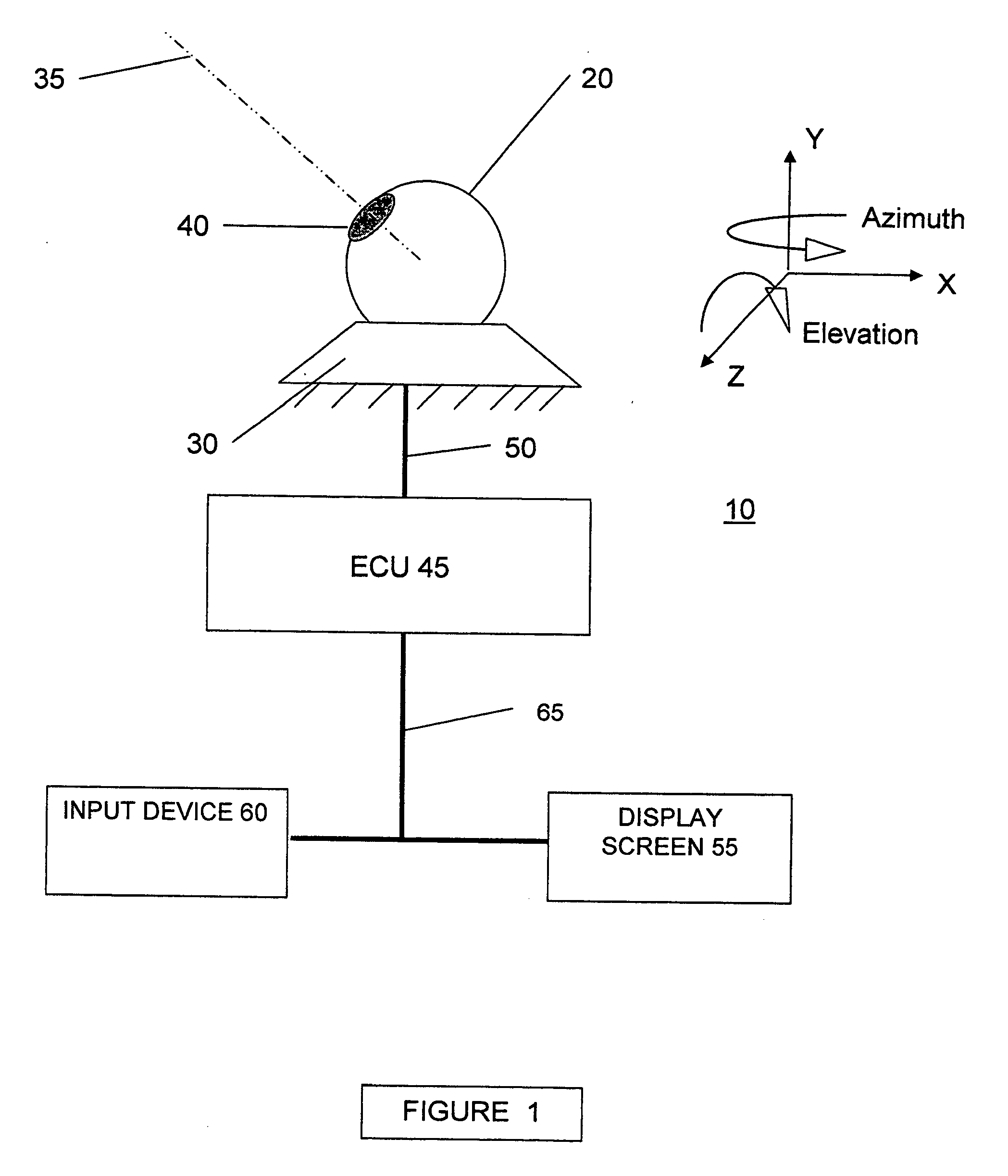
[0022] Referring to FIG. 1, a block diagram depicts a sensor / emitter system 10 according to the present invention. The sensor / emitter system 10 includes a sensor or emitter payload packed inside a spherical ball housing 20. The payload may include sensors and emitters, optical systems, and control elements as required. In general, each sensor or emitter system of the payload includes a field of view, which may be adjustable in size, and a line of sight or pointing direction that is substantially coincident with the center of the field of view. More generally, the payload may comprise any device that has a pointing direction and needs to be rotated about one or two axes to direct the pointing direction at a target object. In FIG. 1, a pointing direction 35 is centered in an aperture 40, formed in the ball housing 20; however, the aperture 40 may comprise more than one aperture, depending upon the payload configuration, and the aperture 40 may be used to receive or emit radiation.

[00...


PUM


Abstract

A rotatable payload support turret for operation in a potentially hazardous environment includes a fixed element attached to a vehicle or fixed structure and a rotatable element, supported for rotation with respect to the fixed element. The turret includes a camera payload having a pointing direction configured to be upwardly pointing. An annular clearance gap formed between the fixed element and the rotatable element is sealed by a conventional gas tight magnetic fluid seal element. A wiper seal is also provided in the clearance gap between the location of the magnetic fluid and the external environment to prevent breakdown of the magnetic fluid by elements of the potentially hazardous environment. The clearance gap may also form a labyrinth seal having up to three legs that are oriented to oppose a gravitational force direction. In addition, the fixed element may include a fluid repelling feature for repelling streams of incoming fluids thereby deflecting elements of the potentially hazardous environment away from an outer opening of the clearance gap.

Description

BACKGROUND OF THE INVENTION [0001] 1. Field of the Invention [0002] The invention provides a method and apparatus for sealing a rotary joint formed between a fixed element and a rotatable element. In particular, a rotary joint formed between a fixed member a rotating member includes a continuous annular clearance gap formed between the fixed member and the rotating member. The clearance gap is sealed to prevent environmental elements from penetrating the clearance gap by providing a combination of sealing elements and features, including a labyrinth seal configuration, a wiper seal and a conventional gas-tight fluid seal within the clearance gap. In addition, the fixed member include features for repelling damaging external environmental elements thrust upon it by wind or wave action. [0003] 2. Description of the Prior Art [0004] Turret mounted airborne camera systems are used in military and public safety for search and rescue, surveillance and reconnaissance. Turret mounted airbor...

Claims


Application Information

Patent Timeline
Patent Type & Authority Applications(United States)
IPC IPC(8): F16J15/447
CPCF16J15/43F16J15/4476Y10T464/30F16M11/10F16M11/2014F16M11/06
Inventor HUGHES, MICHAEL R.SOMMER, THOMAS M.ROSI, RONALD J.
Owner TELEDYNE FLIR LLC
Why Eureka
Try Eureka