Brake Disk Assembly

Inactive Publication Date: 2013-09-19
ASHIMA LTD
View PDF43 Cites 20 Cited by
  • Summary
  • Abstract
  • Description
  • Claims
  • Application Information

AI Technical Summary

Benefits of technology

[0011]Further, a fastener is included to pass through the mounting holes of the supporting plate and the fixing plate to secure the supporting plate and the fixing plate together and to allow limited axial float of the internal teeth, along with other parts, of the friction disk in between the supporting plate and the fixing plate. In particular, the supporting plate is overlapped with the friction disk with

Problems solved by technology

High temperature is generated during clamping and the heat is transmitted to the spokes of

Method used


Image

  • Brake Disk Assembly
  • Brake Disk Assembly
  • Brake Disk Assembly

Examples


Example

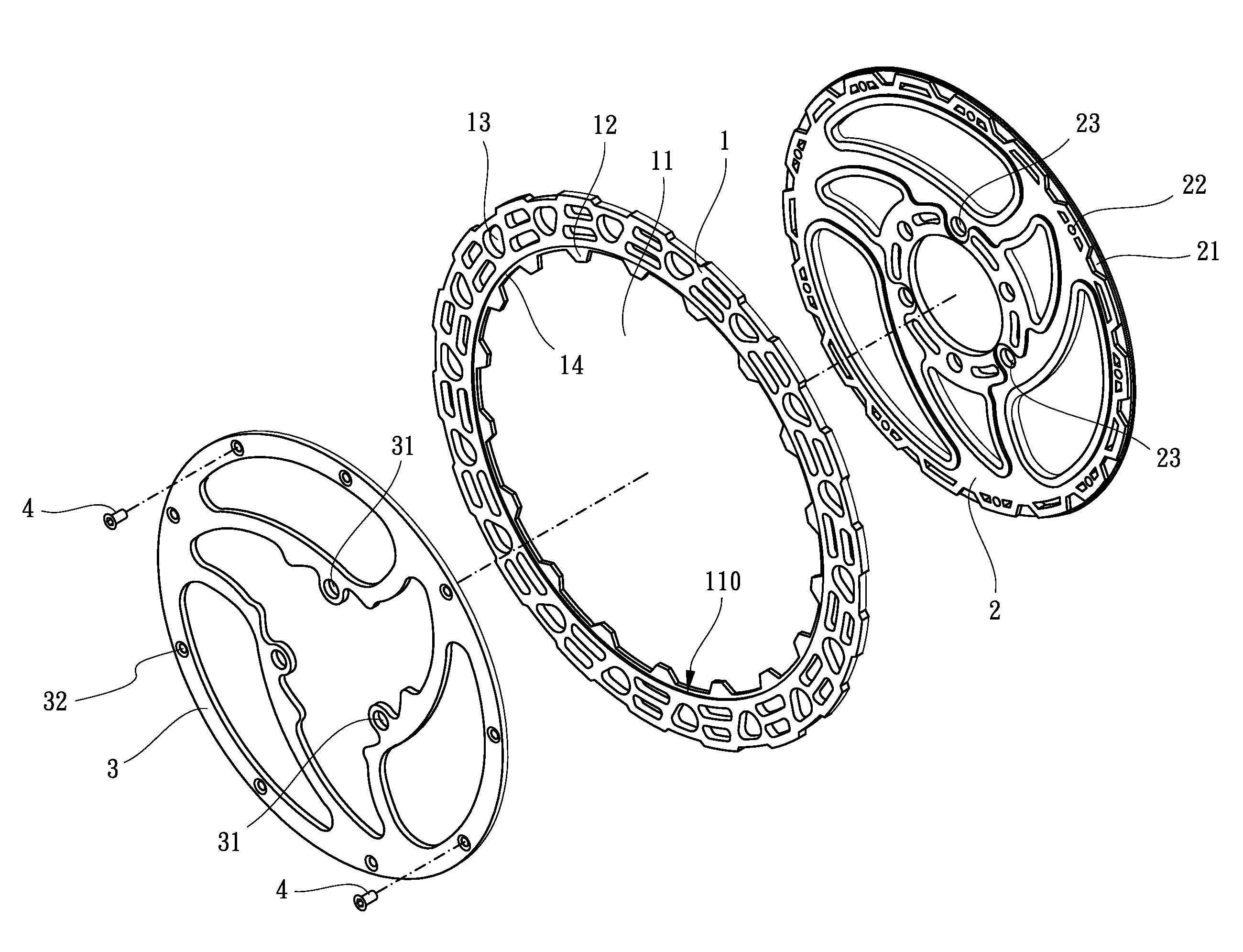
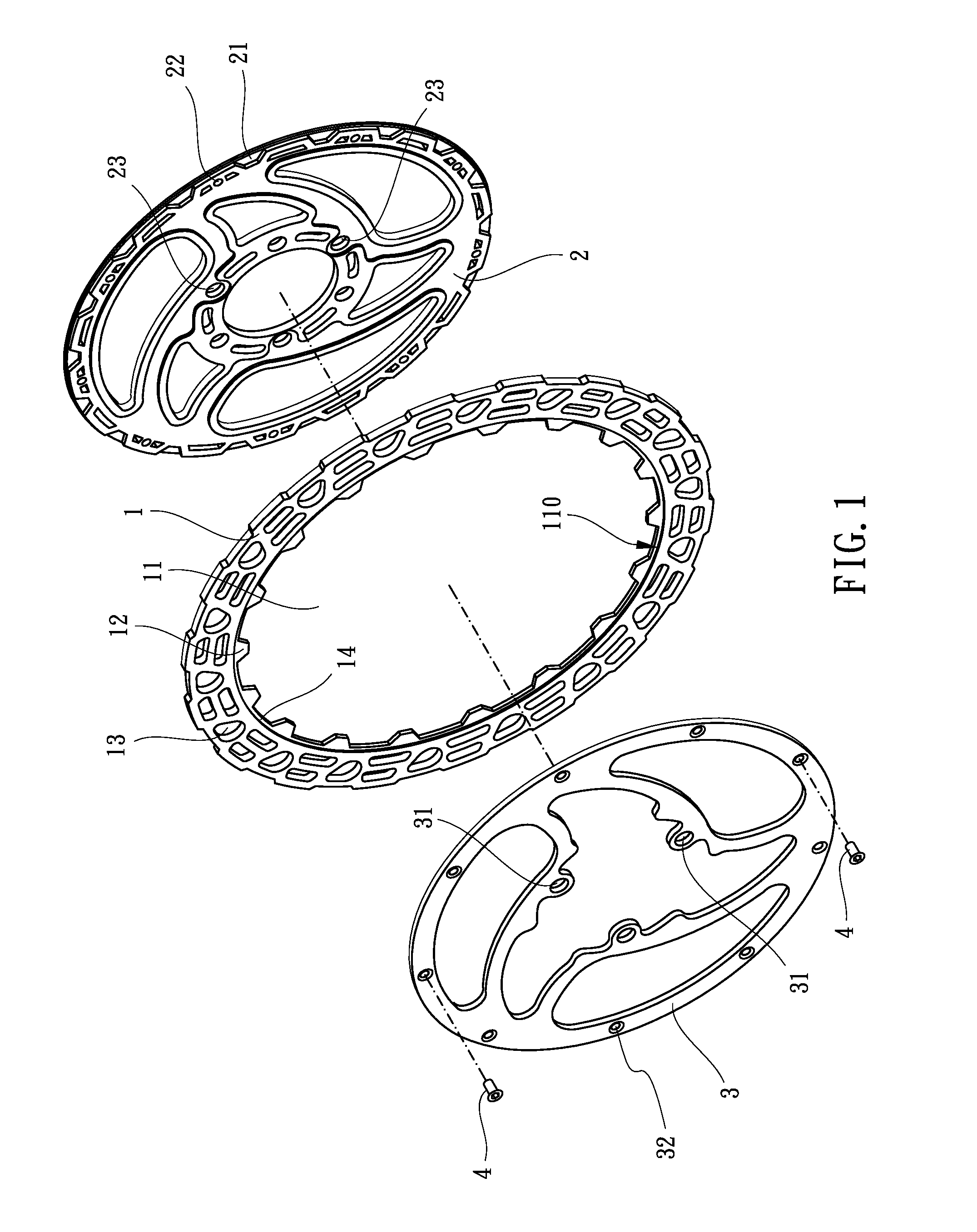
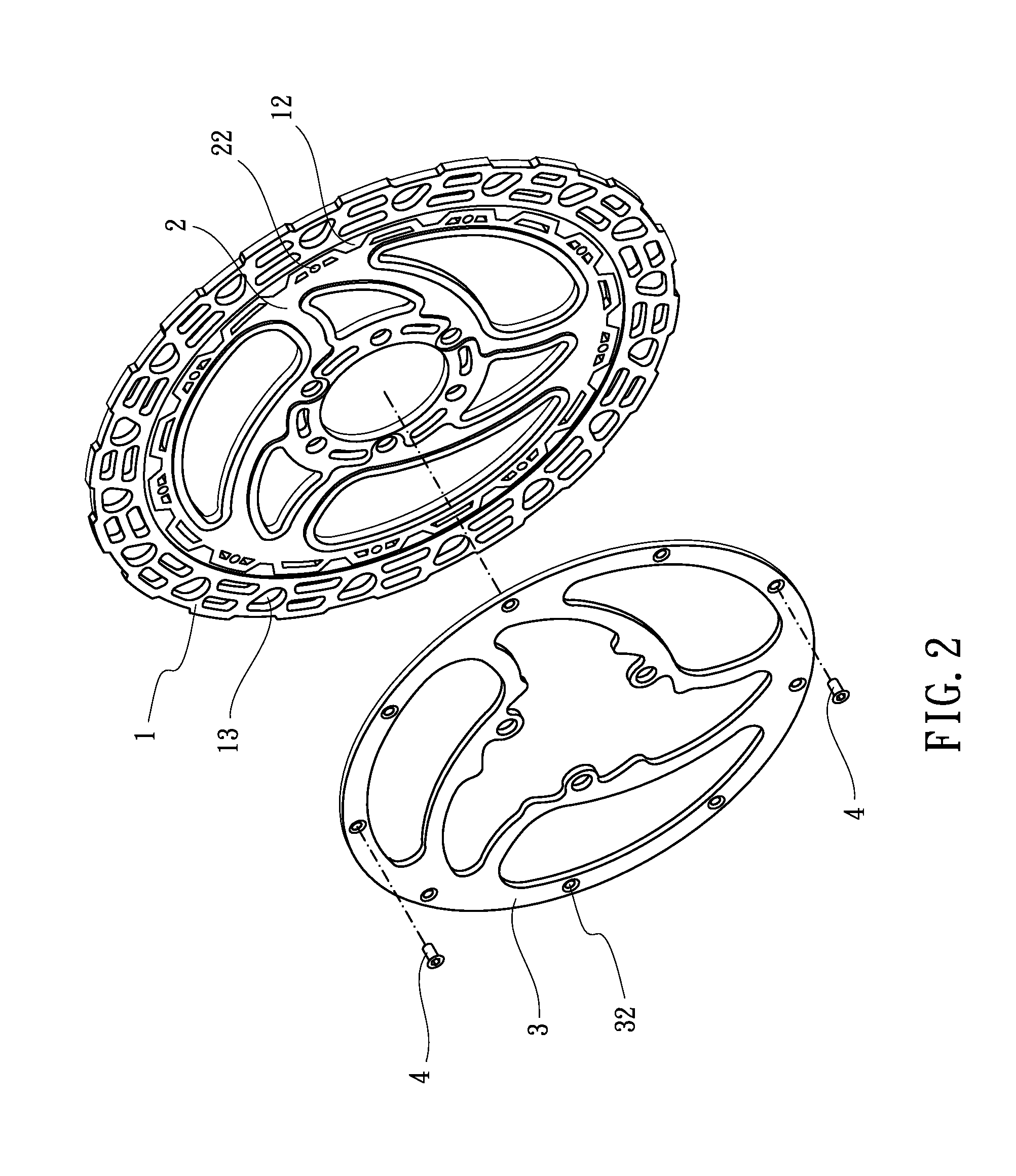
[0021]Referring to FIGS. 1 to 5, the brake disk assembly for a bicycle according to the preferred embodiment of the present invention comprises a friction disk 1, an annular supporting plate 2, an annular fixing plate 3 and a plurality of fasteners 4. The friction disk 1 is coaxially sandwiched in between the supporting plate 2 and the fixing plate 3.

[0022]The friction disk 1 has an internal flange 14 radially extending from an internal circumference 110 thereof, a central aperture 11 defined by the internal circumference 110 thereof, and a plurality of internal teeth 12 extend from the internal flange 14. The internal teeth 12 are formed equidistantly. The friction disk 1 has a plurality of ventilation holes 13 which have different sizes. Heat generated during braking escapes from the brake disk assembly via the ventilation holes 13.

[0023]The supporting plate 2 corresponds in shape to the central aperture 11 of the friction disk 1 to be partly received in one side of the central ap...


PUM


Abstract

A brake disk assembly includes a friction disk clamped between the supporting plate and the fixing plate. The friction disk is axially movable relative to the supporting plate and the fixing plate. The contact area between the friction disk and either one of the supporting plate and the fixing plate is increased to firmly connect the friction disk and the supporting plate and the fixing plate.

Description

CROSS-REFERENCE TO RELATED APPLICATION[0001]This application is a continuation-in-part of U.S. patent application Ser. No. 13 / 272,239, filed Oct. 13, 2011.BACKGROUND OF THE INVENTION[0002]1. Field of the Invention[0003]The present invention relates to a brake disk assembly, and more particularly to a brake disk assembly with a friction disk movably clamped between two plates.[0004]2. Description of the Related Art[0005]A conventional brake disk assembly for a bicycle is fixed to the axle of the wheel and the calipers clamp a friction disk of the brake disk assembly to stop the wheel. High temperature is generated during clamping and the heat is transmitted to the spokes of the bicycle and even soften the brake disk assembly which becomes weak and easily deformed.[0006]An improved conventional brake disk assembly generally includes a supporting plate with a friction disk connected to an external periphery of the supporting plate. The supporting plate has a notch, and the friction pla...

Claims


Application Information

Patent Timeline
IPC IPC(8): F16D65/12
CPCF16D65/12F16D65/123F16D2069/004F16D2065/1368F16D2065/1392F16D2065/1316
Inventor MOORE, WAYNE-IAN
Owner ASHIMA LTD
Why Eureka
Try Eureka