Surface texture of indium-iron grid-shaped spherical composite microcrystal composite layer

A technology of surface texture and composite layer, which is applied in the field of surface texture of indium iron mesh ball composite microcrystalline composite layer, to achieve the effect of reducing fretting fatigue

Inactive Publication Date: 2014-12-24
FUJIAN CHUANZHENG COMM COLLEGE
View PDF9 Cites 22 Cited by
  • Summary
  • Abstract
  • Description
  • Claims
  • Application Information

AI Technical Summary

Problems solved by technology

After years of hard work by domestic scientific and technological workers and engineers, surface texture technology has made significant progress. However, it has not yet been widely used in practice.

Method used


Image

  • Surface texture of indium-iron grid-shaped spherical composite microcrystal composite layer
  • Surface texture of indium-iron grid-shaped spherical composite microcrystal composite layer
  • Surface texture of indium-iron grid-shaped spherical composite microcrystal composite layer

Examples


Embodiment 1

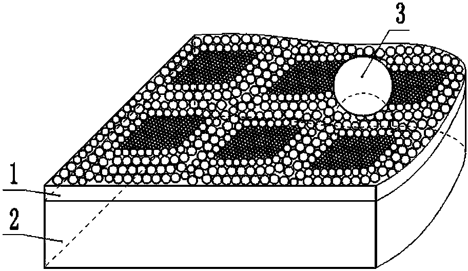
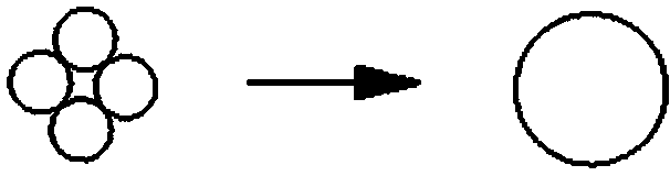
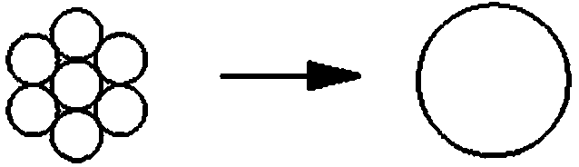
[0026]figure 1 It is a schematic structural view of the surface texture of the indium-iron reticulated ball composite microcrystalline composite layer in Example 1 of the present invention; Fig. 2 (a) is a schematic diagram of the surface texture of the indium-iron reticulated ball composite microcrystalline composite layer in Example 1 of the present invention A schematic diagram of a large indium-iron composite spherical microcrystalline unit composed of four spherical grains closely connected, which is figure 1 One of the microcrystalline units is composed of grids; Fig. 2 (b) shows that more than 4 spherical grains of the surface texture of the indium-iron mesh ball composite microcrystalline composite layer in Example 1 of the present invention are closely connected to form a larger volume of indium Schematic diagram of the microcrystalline unit of the iron composite ball, for figure 1 The grid forms one of the microcrystalline units, the more the number of spherical grai...

Embodiment 2

[0031] figure 1 It is a schematic structural view of the surface texture of the indium iron reticulated ball composite microcrystalline composite layer in Example 1 of the present invention, and Fig. 2 (a) is a schematic diagram of the surface texture of the indium iron reticulated ball composite microcrystalline composite layer in Example 1 of the present invention A schematic diagram of a large indium-iron composite spherical microcrystalline unit composed of four spherical grains closely connected, which is figure 1 One of the microcrystalline units is composed of grids; Fig. 2 (b) shows that more than 4 spherical grains of the surface texture of the indium-iron mesh ball composite microcrystalline composite layer in Example 1 of the present invention are closely connected to form a larger volume of indium Schematic diagram of the microcrystalline unit of the iron composite ball, for figure 1 The grid forms one of the microcrystalline units, the more the number of spherica...


PUM


Abstract

The invention discloses a surface texture of an indium-iron grid-shaped spherical composite microcrystal composite layer. A surface material layer is arranged on a part and mainly comprises larger indium-iron composite spherical microcrystal units of which the indium content exceeds 50% (Wt%) and the total content of indium and iron exceeds 55% (Wt%), each larger indium-iron composite spherical microcrystal unit is formed by close connection of at least four spherical crystal grains or nearly-spherical crystal grains, the larger indium-iron composite spherical microcrystal units are distributed regularly to form a grid, multiple single crystal grains or smaller indium-iron microcrystal units are closely distributed in the grid, each smaller indium-iron microcrystal unit is formed by close connection of at least two spherical crystal grains or nearly-spherical crystal grains, and the surface material layer and a base body material of the part are integrated to form the indium-iron grid-shaped spherical composite microcrystal composite layer; then a surface texture is machined on the part surface provided with the indium-iron grid-shaped spherical composite microcrystal composite layer and consists of multiple surface texture units, and the surface texture of the indium-iron grid-shaped spherical composite microcrystal composite layer is formed.

Description

technical field [0001] The invention relates to the surface texture of an indium-iron mesh ball composite microcrystalline composite layer. Background technique [0002] Friction and wear is one of the main reasons for the failure of machinery and automobiles. About 80% of the failure of mechanical parts is caused by various forms of wear, and the economic loss caused by the failure of mechanical parts reaches billions of yuan. [0003] Surface texture refers to the micro-texture pattern matrix of pits, dents and other micro-texture patterns with a certain size and arrangement processed by certain processing technology on the surface of the friction pair of interconnected contacting mechanical parts. After many years of hard work by many domestic scientific and technological workers and engineers, the surface texture technology has made significant progress, however, it has not yet been widely used in practice. Contents of the invention [0004] The task of the present i...

Claims


Application Information

Patent Timeline
Patent Type & Authority Applications(China)
IPC IPC(8): B32B15/01
Inventor 林绍义
Owner FUJIAN CHUANZHENG COMM COLLEGE
Why Eureka
Try Eureka