Connecting elements for switching devices

A technology for connecting components and switching devices, applied in the direction of protective switch terminals/connections, electric switches, electrical components, etc., can solve the problem of occupying construction space and so on

Inactive Publication Date: 2016-01-20
SIEMENS AG
View PDF6 Cites 0 Cited by
  • Summary
  • Abstract
  • Description
  • Claims
  • Application Information

AI Technical Summary

Problems solved by technology

The disadvantage of this embodiment is that additional components are required for the set nut and additional construction space is required

Method used


Image

  • Connecting elements for switching devices
  • Connecting elements for switching devices
  • Connecting elements for switching devices

Examples


Embodiment Construction

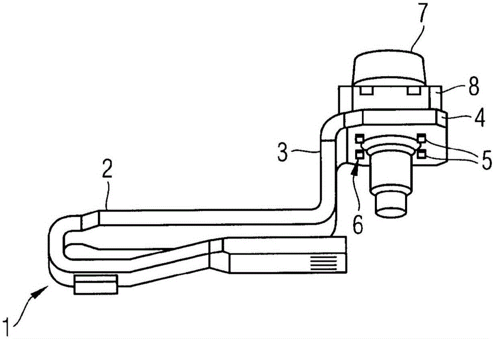
[0031]FIG. 1 shows a connecting clip 1 from the prior art, which has a U-shaped section 2 and an L-shaped section 3 . A bore 5 with an internal thread 6 is arranged in the leg 4 of the L-shaped section 3 . The internal thread 6 is used to accommodate a screw 7 with a web 8 inserted from above. Highly conductive materials with low mechanical strength values ​​are used for the connecting parts. If threads are formed in these materials as described above, the threads are not strong enough for the connecting parts. In addition, there is the possibility that, when connecting the wires, the connecting parts can be accidentally bent.

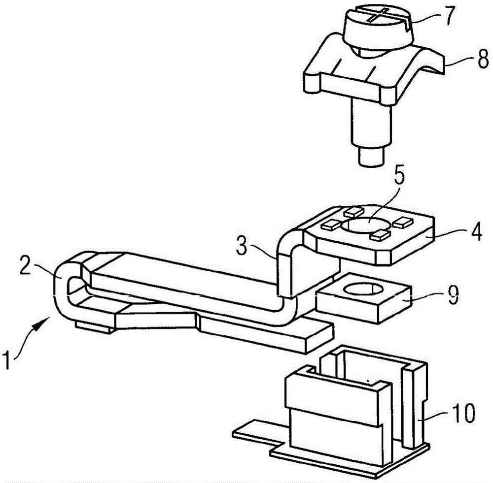
[0032] A further embodiment of a connecting clip with screws from the prior art can be seen from FIG. 2 . Also shown here is a connecting clip 1 with a U-shaped section 2 and an L-shaped section 3 , which has a bore hole 5 in a leg 4 of the connecting clip 1 , into which a screw 7 with a connecting piece 8 can be introduced. in the hole. Arranged ...


PUM


Abstract

The invention relates to a connecting element (11) for a switching device, which has a connecting clip (13) and a screw element (17) with a connecting lug (18). The invention is characterized in that the screw element ( 17 ) is fastened to the connecting clip ( 13 ) via a press-in part ( 12 ).

Description

technical field [0001] The invention relates to a connecting element for a switching device, which has a connecting clip and a screw element with a connecting lug. Background technique [0002] In addition, the force-transmitting connection between the connecting line and the switching device, in particular the low-voltage switching device, is also realized by means of connecting screws. In this case, the threads of these screws are cost-effectively formed in the bores in the connecting parts. [0003] For this purpose, the embodiment shown in FIG. 1 is known from the prior art. FIG. 1 shows a connecting clip 1 which has a U-shaped section 2 and an L-shaped section 3 . A bore 5 with an internal thread 6 is arranged in the leg 4 of the L-section 3 . This internal thread 6 is used to receive a screw 7 with a web 8 introduced from above. Materials with low mechanical strength values ​​and good electrical conductivity are used for the connecting parts. If threads are formed...

Claims


Application Information

Patent Timeline
Patent Type & Authority Patents(China)
IPC IPC(8): H01R4/30
CPCH01H1/5855H01H71/08H01R4/30H01R43/16
Inventor 安德烈亚斯·莱特尔弗兰克·林普勒
Owner SIEMENS AG
Why Eureka
Try Eureka