Optical communication method and device

An optical communication and optical signal technology, applied in the field of optical communication, can solve the problems of insufficient utilization of light and poor mobility support, and achieve the effect of improving utilization efficiency, saving light energy, and ensuring normal communication

Active Publication Date: 2017-09-01
广州慧更思通信科技有限公司
View PDF4 Cites 0 Cited by
  • Summary
  • Abstract
  • Description
  • Claims
  • Application Information

AI Technical Summary

Problems solved by technology

[0004] Based on this, it is necessary to provide an optical communication method and device for the problem that the existing optical communication does not support the mobility of mobile terminals so much that the utilization rate of light is insufficient.

Method used


Image

  • Optical communication method and device
  • Optical communication method and device
  • Optical communication method and device

Examples


Embodiment Construction

[0018] In order to make the object, technical solution and advantages of the present invention clearer, the present invention will be further described in detail below in conjunction with the accompanying drawings and embodiments. It should be understood that the specific embodiments described here are only used to explain the present invention, and do not limit the protection scope of the present invention.

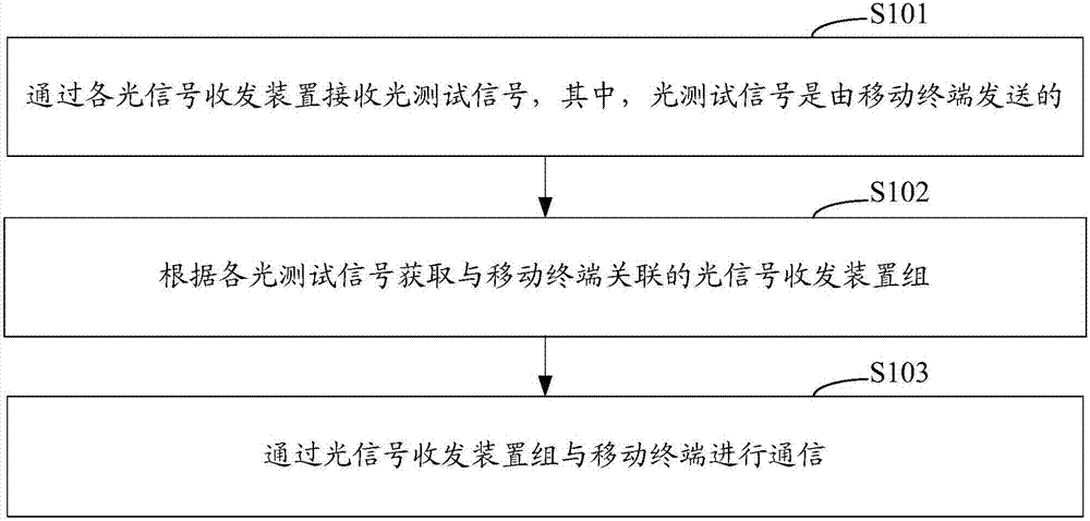
[0019] see figure 1 As shown, it is a schematic flowchart of an optical communication method in an embodiment of the present invention. The optical communication method in this embodiment includes the following steps:

[0020] Step S101: Obtain parameter values ​​of optical test signals received by each optical signal transceiver device, wherein the optical test signal is sent by a mobile terminal;

[0021] Step S102: Determine the optical signal transceiving device group associated with the mobile terminal according to the parameter value of each optical test signal; ...


PUM


Abstract

The invention relates to an optical communication method and optical communication equipment. The optical communication method comprises the steps of: selecting an optical signal transceiving device group associated with a mobile terminal according to parameter values of optical test signals; and communicating with the mobile terminal by utilizing the selected optical signal transceiving device group. Since the position of the mobile terminal changes when the mobile terminal moves, the parameter value of the optical test signal received by each optical signal transceiving device changes, the optical signal transceiving device group associated with the mobile terminal can be dynamically selected by utilizing the parameter values of the optical test signals, the equipment adapts to the mobility of the mobile terminal well, the normal communication is ensured, not all the optical signal transceiving devices generate optical communication power simultaneously, only the optical signal transceiving devices in the selected optical signal transceiving device group generate optical communication power, the light energy is saved, and the utilization efficiency of light is improved.

Description

technical field [0001] The present invention relates to the technical field of optical communication, in particular to an optical communication method and equipment. Background technique [0002] With the popularization of high-brightness light-emitting diode (LED) lighting and the shortage of radio frequency spectrum resources, researchers began to consider using LED lights for both lighting and information transmission, so visible light communication technology emerged. Compared with radio communication technology, visible light communication technology has many advantages: 1. No spectrum license is required; 2. It does not produce electromagnetic radiation that may be harmful to the human body; 3. Based on the line-of-sight transmission path, communication is safer. [0003] However, there are still some shortcomings in optical communication at present, such as the lack of support for the mobility of mobile terminals, and the need for a large number of communication light...

Claims


Application Information

Patent Timeline
Patent Type & Authority Patents(China)
IPC IPC(8): H04B10/116H04B10/079
CPCH04B10/079H04B10/116
Inventor 王昌元黄生叶张娅琳
Owner 广州慧更思通信科技有限公司
Why Eureka
Try Eureka