Pneumatic brake booster with variable force ratio and improved transfer performance

A booster, pneumatic technology, applied in the field of pneumatic brake booster

Inactive Publication Date: 2016-03-09
LUCAS AUTOMOTIVE GMBH
View PDF5 Cites 0 Cited by
  • Summary
  • Abstract
  • Description
  • Claims
  • Application Information

AI Technical Summary

Problems solved by technology

However, the solution proposed by DE19916579A1 shows such a switching behavior when switching from the larger area originally acting on the reaction disk to the reduced area, it is possible that the reduced area takes effect only after a little delay
Correspondingly, the reduction in the input force to be applied by the brake booster user to obtain a large braking force cannot occur as quickly as desired

Method used


Image

  • Pneumatic brake booster with variable force ratio and improved transfer performance
  • Pneumatic brake booster with variable force ratio and improved transfer performance
  • Pneumatic brake booster with variable force ratio and improved transfer performance

Examples


Embodiment Construction

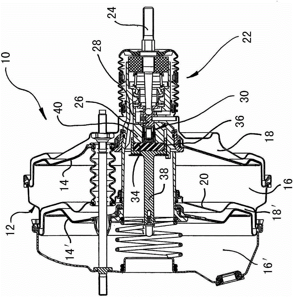
[0026] figure 1 A typical vacuum brake booster 10 is shown in longitudinal section and has a housing 12 which is divided by a movable wall 14 into a vacuum chamber 16 and a working chamber 18 . The brake booster 10 shown here is designed in series, ie it has an additional movable wall 14 ′ which divides the housing 12 part separated by the fixed wall 20 . It is another negative pressure chamber 16' and another working chamber 18'.

[0027] The negative pressure chambers 16 and 16' are always connected with the negative pressure source during the operation of the brake booster 10, while the working chambers 18, 18' can selectively communicate with the negative pressure or the atmospheric pressure. A control valve 22 is used for this, which controls the valve seat in the control valve 22 in accordance with the actuation of a force input mechanism 24, usually connected to a brake pedal (not shown here), in such a way that atmospheric pressure can flow into the working chamber 1...


PUM


Abstract

The booster (10) has a control valve for controlling a pneumatic pressure difference, a force input element (24) for actuating a control valve and a force output element (38) for forwarding braking force. An operating piston support device improves transient response when switching the force transmission ratio between a switching piston and a control valve housing (28) and partly links braking force affecting the switching piston into the control valve housing when the switching piston of the stop is resolved.

Description

technical field [0001] The invention relates to a pneumatic brake booster. Background technique [0002] Such a brake booster designed for motor vehicles in the form of a vacuum brake booster is known from DE 199 16 579 A1. [0003] Generally, the pneumatic brake booster has a fixed force transmission ratio, that is, the operating force input into the brake booster by the contact input mechanism is transmitted from a smaller area corresponding to the input mechanism to a force corresponding to the force. The larger area of ​​the output mechanism is mostly centered with a so-called reaction disk made of an elastomeric material that behaves like a fluid. However, in some cases, such as sudden braking, it is desirable to provide the user with as large a braking force assist effect as possible, so as to generate as large a braking pressure as possible based on a certain input force. [0004] Therefore, it is proposed in said DE 199 16 579 A1 to further reduce the smaller area ...

Claims


Application Information

Patent Timeline
Patent Type & Authority Patents(China)
IPC IPC(8): B60T13/575B60T13/57B60T13/569
CPCB60T13/575
Inventor D·洛佩兹H-M·吉斯
Owner LUCAS AUTOMOTIVE GMBH
Why Eureka
Try Eureka