Medical Instrument

a technology of instruments and instruments, applied in the field of medical instruments, can solve the problems of increasing the diameter of the instrument in the area between the push-pull rod and the tool, not always available, and the inability to use known instruments in all operations

Inactive Publication Date: 2008-01-17
KARL STORZ GMBH & CO KG
View PDF16 Cites 2 Cited by
  • Summary
  • Abstract
  • Description
  • Claims
  • Application Information

AI Technical Summary

Benefits of technology

[0011] It is further proposed with the invention that the sectional point of the central axes of the jointed gear of one jaw member forms the point of rotation of the jaw members. This virtual point of rotation that moves according to the position of the jaw members with respect to one another has the effect that the gear mechanism for powering the jaw members independently of the position of the jaw members to one another, always lies within the instrument diameter, so that a medical instrument of this configuration can be used ...

Problems solved by technology

These medical instruments have proved themselves in practice; however, in tight spaces—for instance, in endoscopic surgery—that have the disadvantage that the jointed gear in opening the jaw members rotate outward and th...

Method used


Image

  • Medical Instrument
  • Medical Instrument
  • Medical Instrument

Examples


first embodiment

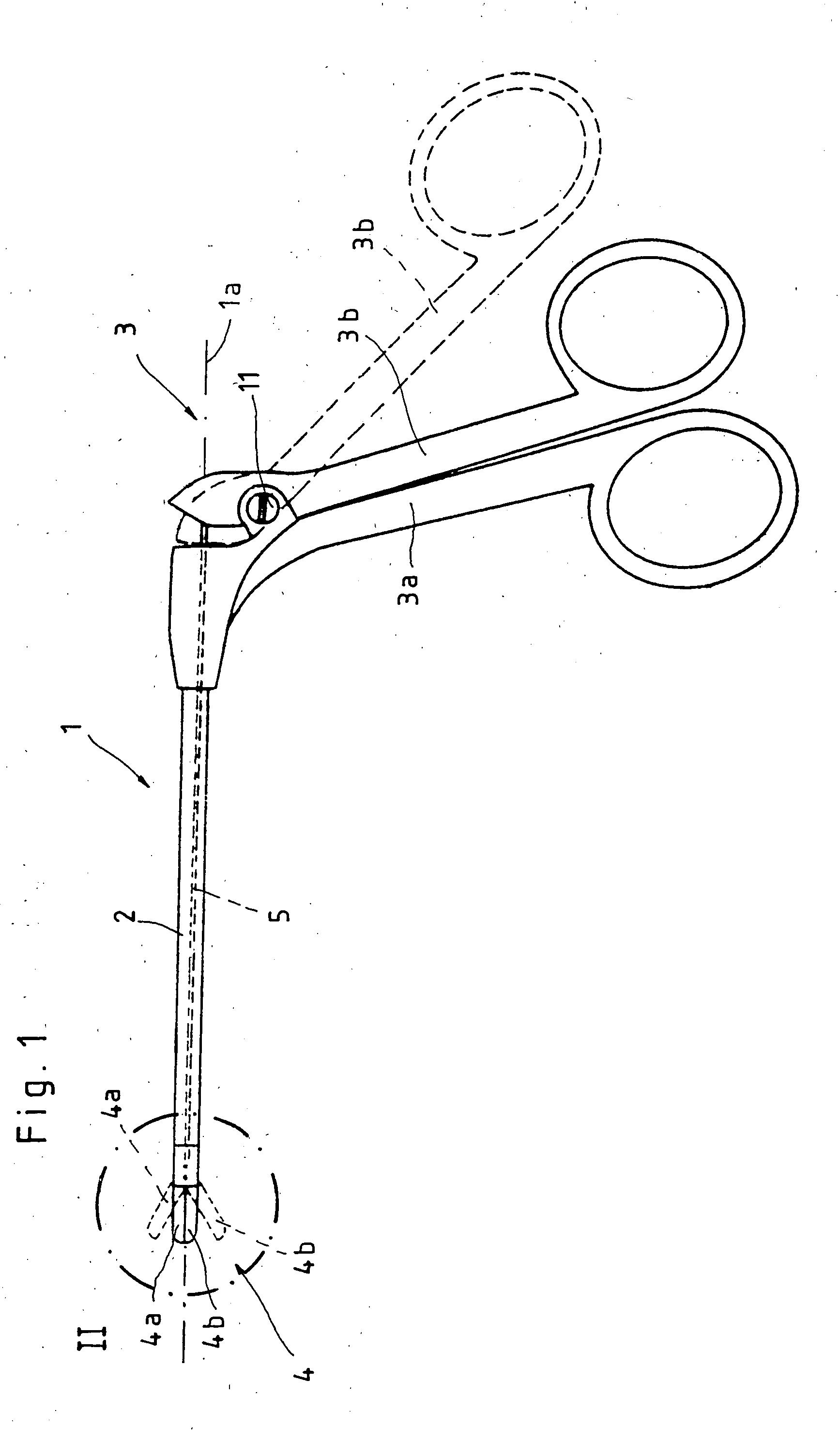
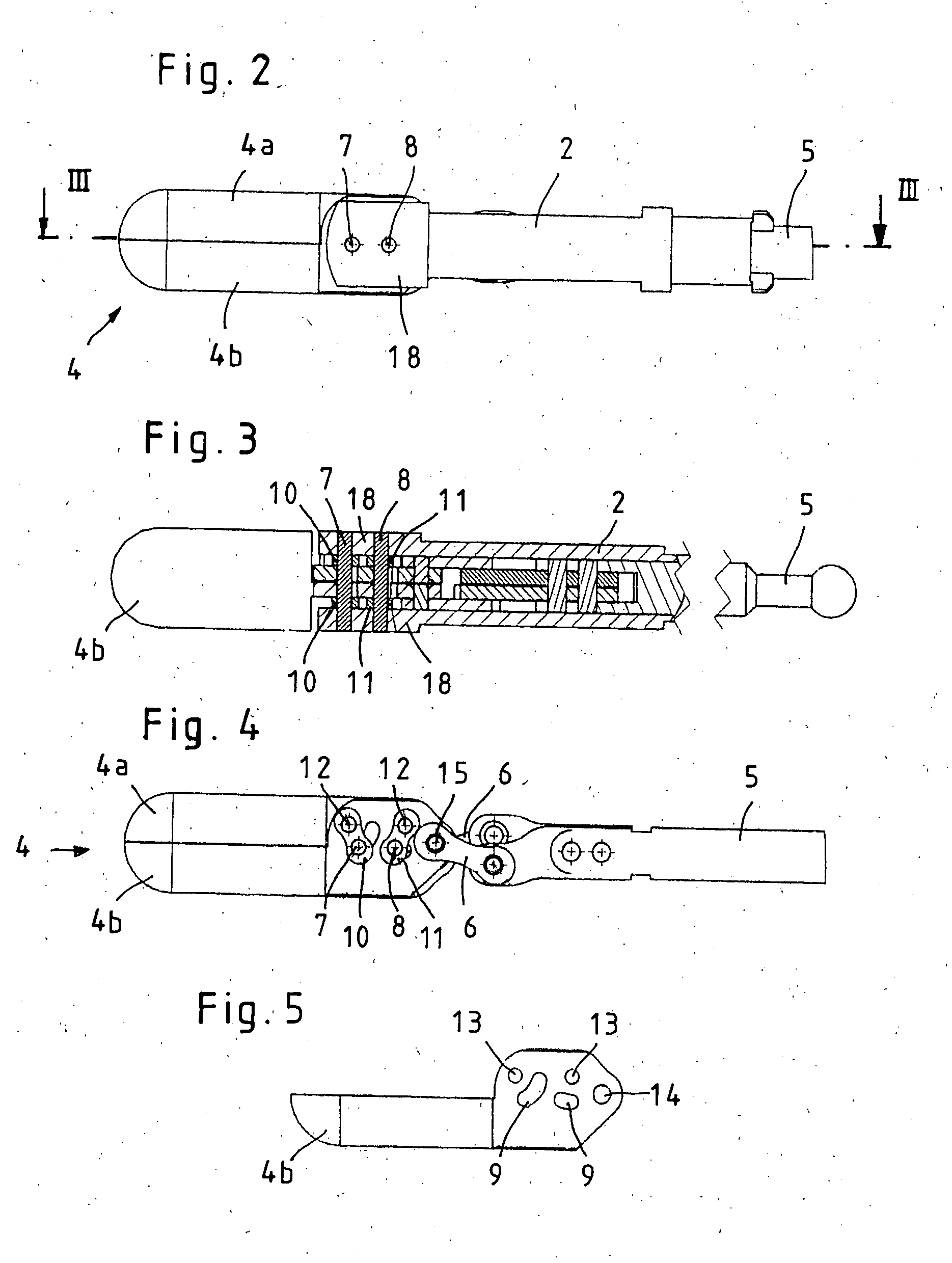
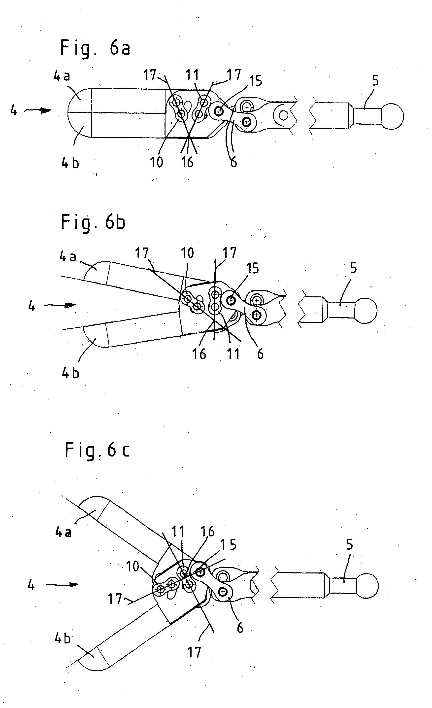
[0038] To ensure that in the first embodiment shown in FIGS. 2 through 6c, on the one hand a sufficient transmission of force can be applied for the required cutting or clamping forces of the push-pull rod 5 on the jaw members 4a and 4b and, on the other hand, the dimensions of the instrument are not enlarged by the gear mechanism, the jaw members 4a and 4b are positioned so that they control two axles 7 and 8, which in turn are mounted parallel to one another and perpendicular to the instrument longitudinal axis 1a in the shaft 2, so that in the jaw members 4a and 4b arc-shaped spaces are opened up for the axles 7 and 8.

[0039] The rotatable jaw members 4a and 4b are coupled with the axles 7 and 8 positioned in the shaft 2 by means of two pivot gears 10 and 11 per jaw member 4a, 4b, so that the pivot gears 10, 11 ensure an increased force transmission ratio between the push-pull rod 5 and the jaw members 4a, 4b.

[0040] The structure of the jaw members 4a, 4b and their coupling with ...

second embodiment

[0045] the power transmission mechanism, shown in FIGS. 7a to 7c, between the push-pull rod 5 and the jaw members 4a and 4b is differentiated from the previously described embodiment in that in this embodiment each of the two jaw members 4a and 4b.

[0046] The second embodiment of the force transmission mechanism, shown in FIGS. 7a through 7c, between the push-pull rod 5 and the jaw members 4a and 4b, is distinguished from the previously described embodiment in that in this version each of the two jaw members 4a and 4b is coupled with the shaft 2 by only one pivot gear 10.

[0047] In this embodiment this coupling is performed in such a way that every pivot gear 10 of each jaw member 4a, 4b is rotatably mounted with one end immovably positioned on a stud 12 situated on the respective jaw member 4a, 4b and with the other end rotatably mounted on an axle neck 19 positioned immovably on the side of the shaft closer to this jaw member 4a, 4b.

[0048] As an alternative to the one-sided mount...

third embodiment

[0050]FIGS. 8a and 8b show the force transmission mechanism between the push-pull rod 5 and the jaw members 4a and 4b. This embodiment, in contrast to the two previously described structural embodiments, has the essential difference that the push-pull rod 5 is not connected with the jaw members 4a and 4b by an intermediate toggle joint 6 but rather directly by means of a bearing bolt 22.

[0051] In addition, the third embodiment, shown in FIGS. 8a and 8b, is distinguished from the two versions previously described and shown in FIGS. 7a through 7c in that here no guide tracks for bearing pins are provided in the jaw members 4a and 4b. Instead, the rotatable jaw members 4a, 4b are coupled with the shaft 2 entirely by one pivot gear 10 each, which is mounted with one end rotatably but immovably on a stud 12 mounted on the respective jaw member 4a, 4b and with the other end rotatably mounted on an axle neck 9 positioned immovably on the side of the shaft closer to this jaw member 4a, 4b. ...


PUM


Abstract

The invention relates to a medical instrument having on its proximal end a shaft with a handle consisting of two gripping members and on its distal end a tool consisting of two jaw members and in which, to open and close the tool, at least one jaw member can rotate with respect to the other jaw member around a point of rotation by means of a push-pull rod and in which the push-pull rod is connected on the proximal side with a rotatable gripping member of the handle. To produce a medical instrument that can be used even in closely confined spaces and with sufficient transmission of force, it is proposed with the invention that the point of rotation should be configured as a variable, virtual point of rotation that is dependent on the position of the jaw members to one another.

Description

FIELD OF THE INVENTION [0001] The invention relates to a medical instrument having on its proximal end a shaft with a handle consisting of two gripping members and on its distal end a tool consisting of two jaw members and in which at least one jaw member can rotate with respect to the other jaw member around a point of rotation by means of a push-pull rod to open and close the tool and in which the push-pull rod is connected on the proximal side with a rotatable gripping member of the handle. BACKGROUND OF THE INVENTION [0002] Generic medical instruments are often used in the art as gripping, holding, and / or cutting tools. Thus the jaw members can comprise blades for severing tissue or blunt surfaces for holding severed tissue, for instance, or to clamp off blood vessels. [0003] A common element among these medical instruments is that both jaw members of the tool mounted on the distal end of the shaft can rotate around a common point of rotation. For opening and closing the jaw mem...

Claims


Application Information

Patent Timeline
IPC IPC(8): A61B17/28A61B17/00
CPCA61B10/06A61B2017/2939A61B2017/2936A61B17/29
Inventor SUMMERER, SABINE
Owner KARL STORZ GMBH & CO KG
Why Eureka
Try Eureka