Gas, liquid and solid three-phase separator for sewage anaerobic biological treatment

A three-phase separator and biochemical treatment technology, which is applied in the field of solid three-phase separator, liquid and gas, can solve the problems of poor separation effect and influence of solid phase granular sludge

Active Publication Date: 2013-02-06
SHANDONG PACIFIC ENVIRONMENTAL PROTECTION
View PDF6 Cites 10 Cited by
  • Summary
  • Abstract
  • Description
  • Claims
  • Application Information

AI Technical Summary

Problems solved by technology

[0012] The purpose of the present invention is to solve the technical defects in the above-mentioned three-phase separator, and change the design concept of the three-phase mixture entering (rising) and sludge returning (falling) through the same channel from the design concept ; From the design performance, an independent sludge descending channel and a separate settling zone are obtained, which solves the problem of the solid phase settling movement affected by the upward flow velocity in the current three-phase separator and the separation of solid phase particles (or flocculent) sludge The difficult problem of poor effect, thus greatly improving the mud-water separation effect of the three-phase separator

Method used


Image

  • Gas, liquid and solid three-phase separator for sewage anaerobic biological treatment
  • Gas, liquid and solid three-phase separator for sewage anaerobic biological treatment
  • Gas, liquid and solid three-phase separator for sewage anaerobic biological treatment

Examples


Embodiment Construction

[0048] The present invention will be further described below in conjunction with accompanying drawings and examples.

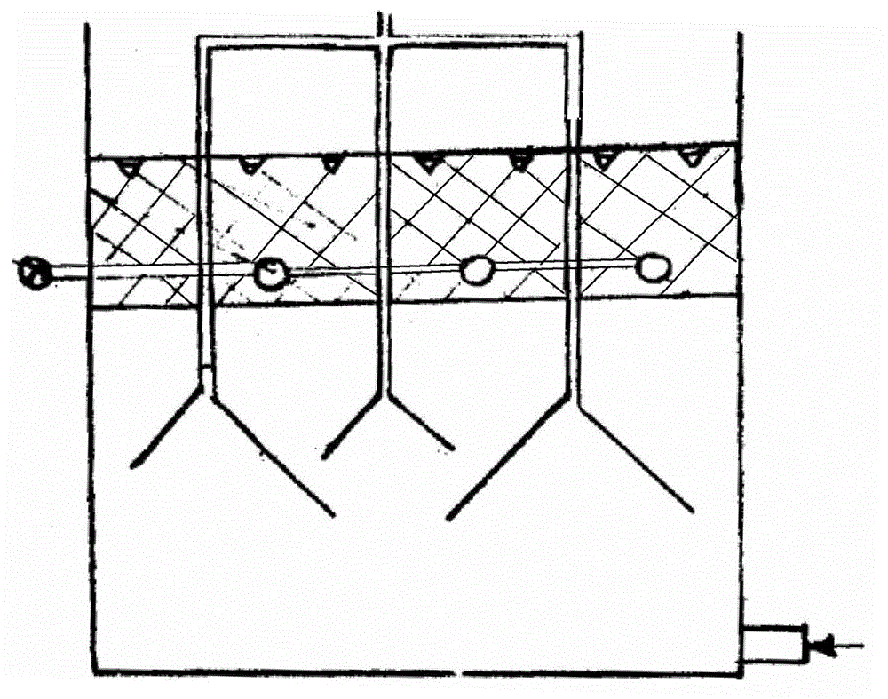
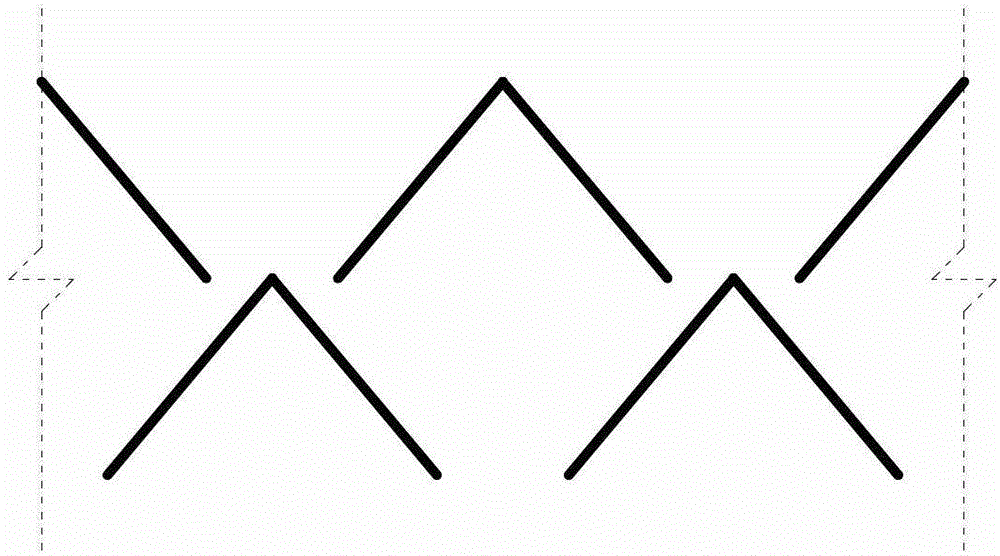
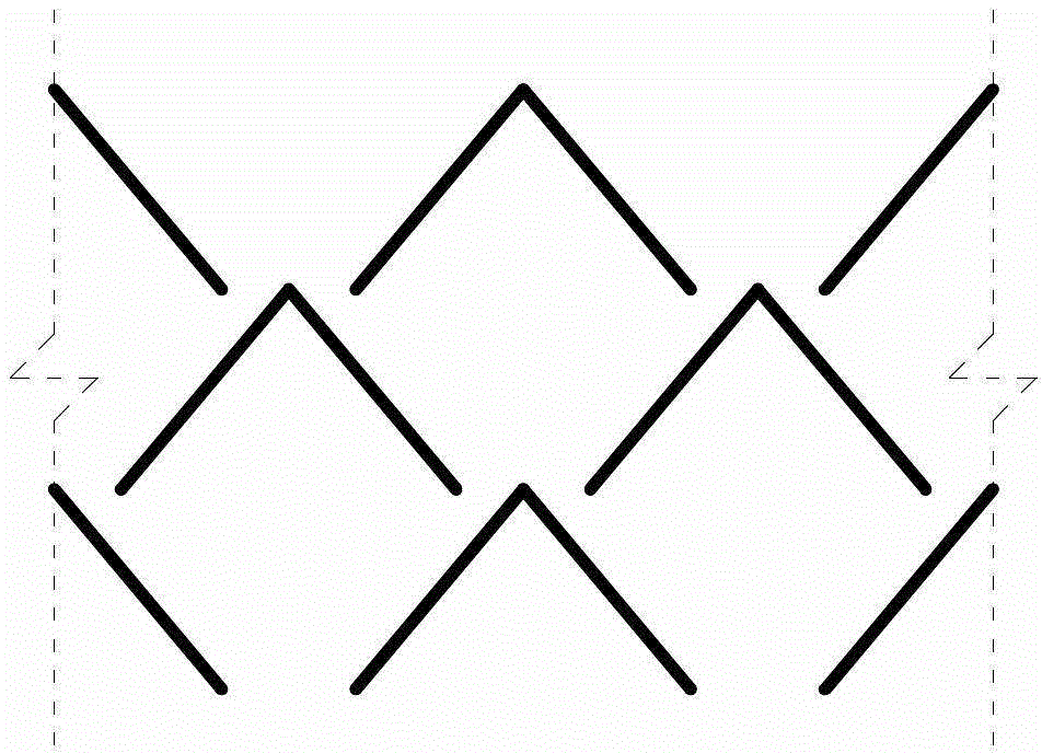
[0049] Such as image 3 As shown, the gas, liquid and solid three-phase separator used in the anaerobic biochemical treatment of sewage includes several single-layer inverted triangular gas collection chambers 1, and each single-layer inverted triangular gas collection chamber 1 is equipped with Two symmetrical L-shaped deflectors arranged in a figure-eight shape, and the lengths of the L-shaped deflectors below the adjacent single-layer inverted triangular plenum 1 are not equal, and the longer L-shaped deflector It is called the L-shaped long deflector 2, and the shorter L-shaped deflector is called the L-shaped short deflector 3, and both are collectively called the L-shaped deflector; the two adjacent L-shaped long deflectors A complete independent sludge settlement area 5 is formed between the plate 2 and the L-shaped short deflector 3; the gap between t...


PUM

PropertyMeasurementUnit
angleaaaaaaaaaa
lengthaaaaaaaaaa
lengthaaaaaaaaaa

Abstract

The invention discloses a gas, liquid and solid three-phase separator for sewage anaerobic biological treatment. The gas, liquid and solid three-phase separator for the sewage anaerobic biological treatment comprises a plurality of single-layer inverted-triangular gas collection chambers; two symmetrical flow guide plates which are arranged in an eight shape are arranged under the central line of each single-layer inverted-triangular gas collection chamber; the lengths of the flow guide plates under the adjacent two single-layer inverted-triangular gas collection chambers are different; the longer L-shaped flow guide plates are called as long L-shaped flow guide plates, and the shorter L-shaped flow guide plates are call as short L-shaped flow guide plates; a complete independent sludge sedimentation area is formed between the adjacent long L-shaped flow guide plate and the short L-shaped flow guide plate; and gaps between the tops of the flow guide plates and the triangular gas collection chambers are used as channels for the degassed sludge to enter the independent sludge sedimentation area; and gaps between the lower ends of the short L-shaped flow guide plates and the adjacent long L-shaped flow guide plates form an independent channel which is communicated with the independent sludge sedimentation area. The gas, liquid and solid three-phase separator for the sewage anaerobic biological treatment is simple in structure, small in size, low in cost, convenient to manufacture, install and maintain and high in separation efficiency.

Description

technical field [0001] The invention relates to a sewage treatment device, in particular to a gas, liquid and solid three-phase separator used in sewage anaerobic biochemical treatment. Background technique [0002] The "three-phase" in the so-called three-phase separator refers to gas, liquid, and solid (that is, biogas, sewage, granular or flocculent sludge in sewage anaerobic treatment), and it is more called gas-solid in foreign literature. Separator (GSS for short). [0003] The three-phase separator has two main functions: [0004] 1) Collect the biogas generated from the reaction chamber below the three-phase separator to prevent the biogas bubbles from rising to the sedimentation area above the three-phase separator; [0005] 2) Form a good settling environment for the settling area above the three-phase separator, so that granular (or flocculent) sludge can settle in the settling area above the three-phase separator, and pass through the three-phase separator smoo...

Claims


Application Information

Patent Timeline
Patent Type & Authority Applications(China)
IPC IPC(8): C02F3/28
Inventor 朱杰高杨庆宾
Owner SHANDONG PACIFIC ENVIRONMENTAL PROTECTION
Why Eureka
Try Eureka