Novel multi-fuel sleeve type lime kiln

A multi-fuel, sleeve-type technology, applied in the field of lime kiln, can solve the problems of low daily output and low calcination efficiency, and achieve the effects of increasing capacity, increasing calcining efficiency, and improving calcining uniformity

Inactive Publication Date: 2013-02-06
BO GUANG THERMAL ENERGY
View PDF2 Cites 4 Cited by
  • Summary
  • Abstract
  • Description
  • Claims
  • Application Information

AI Technical Summary

Problems solved by technology

[0003] The purpose of the present invention is to provide a multi-fuel sleeve type lime kiln with high calcination efficiency, uniform calcination, an

Method used


Image

  • Novel multi-fuel sleeve type lime kiln

Examples


Example Embodiment

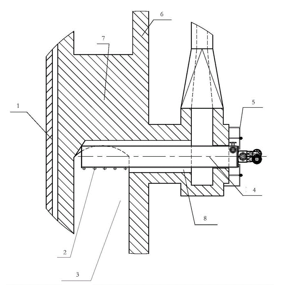
[0010] figure 1 As shown, the main structure of the multi-fuel sleeve lime kiln is the same as the prior art. It is composed of a kiln shell 6, an upper inner sleeve (not shown) located in the kiln shell, and a lower inner sleeve 1, and a calcining annular channel 3 is formed between the kiln shell 6 and the lower inner sleeve 1. The annular passage 3 is provided with an arch bridge 7 and two rows of spaced apart combustion chambers 8. The multi-fuel sleeve lime kiln of the present invention is provided with a combustion beam 4 in the combustion chamber, and the combustion beam 4 extends from the wall of the kiln shell into the annular passage 3; the part of the combustion beam extending into the annular passage 3 Set with burner 2. The combustion beam can use the existing structure in the prior art, and the fuel used can be pulverized coal, coal gas, heavy oil, etc. The end of the combustion beam in the present invention protrudes from the kiln body and a fixed platform 5 i...


PUM


Abstract

The invention discloses a novel multi-fuel sleeve type lime kiln which is composed of a kiln shell and upper and lower inner sleeves, wherein the upper and lower inner sleeves are arranged in the kiln shell; a calcining circular passage is formed between the kiln shell and the upper and lower inner sleeves; burning chambers which are distributed into two rows with one above the other are arranged in the circular passage at intervals; burning beams are arranged in the burning chambers; each burning beam extends into the circular passage from the wall of the kiln shell; and the beam body part of each burning beam extending into the circular passage is provided with a nozzle. By adopting the sleeve type lime kiln, good calcining effect can be still obtained under the condition that the distance between the kiln shell and the upper and lower inner sleeves is increased, thus, the capacity of limestone can be greatly improved through greatly enlarging the width of the circular passage, and the daily yield of a calcining kiln is improved further. With the adoption of the multi-fuel sleeve type lime kiln, the daily yield of the calcining kiln can reach 800 tons, the limitation that the highest daily yield of the existing kiln type is 600 tons is broken through thoroughly, and economic benefits are extremely outstanding.

Description

technical field [0001] The invention relates to a lime kiln, in particular to a multi-fuel sleeve type lime kiln. Background technique [0002] The existing sleeve-type lime kiln is composed of a kiln shell and upper and lower inner sleeves located in the kiln shell. A calcining annular passage is formed between the kiln shell and the upper and lower inner sleeves; There are two upper and lower rows of upper and lower combustion chambers distributed at intervals. CN 102072648 A discloses a sleeve-type lime kiln in which pulverized coal burners and gas burners are distributed on the outer end walls of the upper and lower combustion chambers. The air flow then enters the circular channel to circulate the material for calcination. The kiln with this structure has poor calcination uniformity, which leads to the maximum daily output of the sleeve kiln being only 600 tons, which cannot meet the production demand. Contents of the invention [0003] The purpose of the present in...

Claims


Application Information

Patent Timeline
IPC IPC(8): C04B2/12
Inventor 宋军保杨金凯刘贵春郭黎明
Owner BO GUANG THERMAL ENERGY
Why Eureka
Try Eureka