Switching mechanism for dial-block type valve electric actuator

A technology of electric valve and switching mechanism, which is applied in the direction of valve device, valve operation/release device, engine components, etc. It can solve the problems of poor reliability, complex structure of switching mechanism, easy misoperation, etc., and achieve the effect of simple structure

Inactive Publication Date: 2013-02-06
常州电站辅机股份有限公司
View PDF0 Cites 2 Cited by
  • Summary
  • Abstract
  • Description
  • Claims
  • Application Information

AI Technical Summary

Problems solved by technology

[0003] The technical problem to be solved in the present invention is that the switching mechanism of the existing valve electric device has complex structure, large switching force, and the switching handle cannot be automatically reset, which is easy to misuse and has poor reliability

Method used


Image

  • Switching mechanism for dial-block type valve electric actuator
  • Switching mechanism for dial-block type valve electric actuator
  • Switching mechanism for dial-block type valve electric actuator

Examples


Embodiment Construction

[0017] The preferred technical solutions of the present invention will be described in detail below in conjunction with the accompanying drawings.

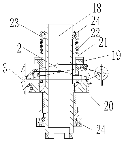
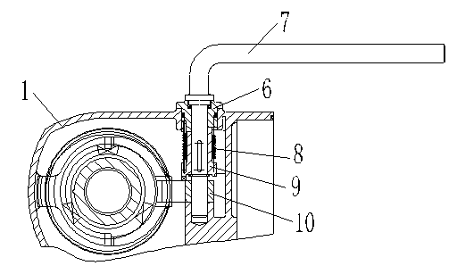
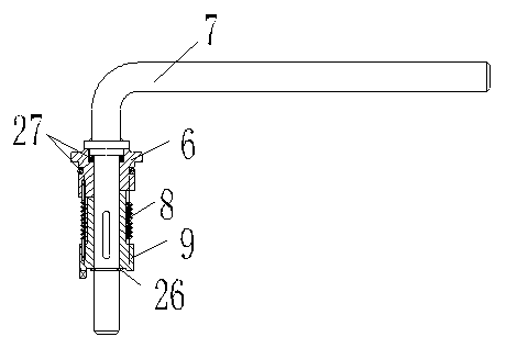
[0018] As shown in the figure, the switching mechanism for the dial-type valve electric device of the present invention includes a switching handle part, a dial part, a dial frame and an output shaft part. The output shaft part is installed in the box body 1, and the dial The block frame 2 is installed on the output shaft part, one end is installed on the stand 3 of the box wall, and is connected to the stand 3 in rotation, and the other end has a groove 4, and the switching handle part is installed on the output shaft One side of the part, the shift block part is installed at one end of the switch handle part, and the pin 5 on the shift block part is connected to the slot 4 of the shift block frame; the switch handle part includes a support seat 6, Handle 7, torsion spring 8 and adapter 9, one end of described handle 7 is install...


PUM


Abstract

The invention discloses a switching mechanism for a dial-block type valve electric actuator. The switching mechanism comprises a switching handle component, a dial-block component, a dial-block frame and an output shaft component, wherein the output shaft component is arranged inside a box body; the dial-block frame is arranged on the output shaft, one end of the dial-block frame is arranged on a lug of a box body wall and rotationally connected with the lug, and the other end is provided with a groove; the switching handle component is installed at one side of output shaft component; and the dial-block component is installed at one end of the switching handle component; a pin on the dial-block component is connected to the groove of the dial-block frame. By adopting a structure of the switching mechanism, a switching force is reduced; a switching handle can be automatically reset without misoperation after being pressed down; and therefore, the switching mechanism is simple and compact in structure.

Description

technical field [0001] The invention relates to a switching mechanism for a shifting block type valve electric device. Background technique [0002] All valve electric devices should be equipped with a manual operating mechanism. In order to change the working conditions, there should also be a switching means, that is, a manual → electric switching mechanism. According to the function, it can be divided into three forms: full manual switching, fully automatic switching and semi-automatic switching. According to the installed position, it can be divided into two forms: switching on the high-speed shaft and switching on the low-speed shaft. When the output torque of the valve electric device is small, a semi-automatic switching mechanism switching on the low-speed shaft is generally used. The switching form used in the low-speed shaft switching of the original valve electric device: the multi-stage gear transmission of the motor to the worm shaft, the worm shaft has a worm ...

Claims


Application Information

Patent Timeline
Patent Type & Authority Applications(China)
IPC IPC(8): F16K31/05F16K31/53
Inventor 马秀武蒋亚培孟晶晶
Owner 常州电站辅机股份有限公司
Why Eureka
Try Eureka