
One-way pressure dynamic loading device

A dynamic loading and one-way pressure technology, which is applied in the testing of measuring devices, instruments, machines/structural components, etc., can solve the problems of unrealistic loading force, unstable loading force, and excessive pressure, etc., and achieve the overall goal of the device. The effect of compact structure, smooth movement and low friction

Inactive Publication Date: 2014-11-26
TSINGHUA UNIV
View PDF7 Cites 0 Cited by
  • Summary
  • Abstract
  • Description
  • Claims
  • Application Information

AI Technical Summary

Problems solved by technology

The existing mechanical one-way pressure loading device is mainly loaded by a screw or a counterweight, which cannot realize accurate real-time control of the loading force, and will generate additional tangential friction load when the loading object moves, so it is generally only suitable for static Loading; hydraulic loading is stable and easy to control, but its dynamic characteristics are poor, and additional hydraulic pumps are required, the equipment and pipelines are complex, maintenance is difficult, and reliability is low; the equipment required for pneumatic loading is simpler than hydraulic loading, and its dynamic performance is slightly Good, but the applied pressure should not be too large, and the loading force is unstable and the loading accuracy is low
[0004] None of the above-mentioned loading devices can fully realize the requirements of high-precision, fast-response, and high-reliability one-way controllable pressure loading

Method used


Image

  • One-way pressure dynamic loading device
  • One-way pressure dynamic loading device

Examples


Embodiment 1

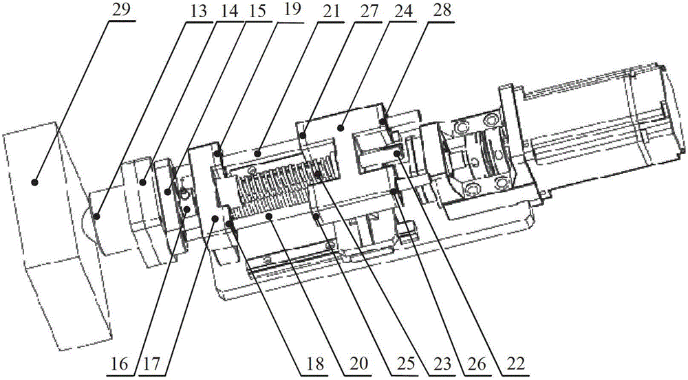
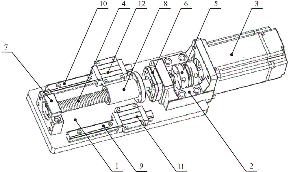
[0020] Such as figure 2 As shown, the structure of the servo transmission mechanism is: a motor support base 2 is fixed at one end of the base plate 1, and the servo motor 3 is fixed on the motor support base 2; the ball screw 4 is connected to the rotating shaft of the servo motor 3 through a coupling 5; The end of the ball screw 4 close to the coupling 5 is supported by the fixed end 6 of the ball screw fixed on the motor support base 2, and the other end is supported by the support end 7 of the ball screw fixed on the bottom plate 1. Support rotation; the ball screw 4 is sleeved with a flange-type screw nut 8; on both sides of the ball screw 4, there are first sliding guide rails 9 and second sliding guide rails 10 arranged in parallel and at equal intervals. A first slider 11 is arranged on a sliding guide rail 9, and a second slider 12 is arranged on a second sliding guide rail 10; the lead screw nut 8, the first slider 11 and the second slider 12 are positioned perpendi...


PUM


Abstract

The invention discloses a one-way pressure dynamic loading device and belongs to the technical field of mechanical manufacturing. The structure of the one-way pressure dynamic loading device provided by the invention is as follows: a servo motor is fixed on a base plate; the servo motor is connected with a ball screw through a coupler; a screw nut is sleeved on the ball screw; two sliding guide rails which are respectively provided with a sliding block are arranged on the two sides of the ball screw; the base plate fixed with a loading ball is fixed on a loading base; a pressure sensor is located between the loading base and a connecting base; a cylindrical straight guide rail is respectively mounted in each of the holes on the two sides of a sliding support base; a guiding rod sleeved with a loading spring passes through the hole in the middle of the sliding support base and is connected with the connecting base; and the sliding support base is connected with the screw nut and the two sliding blocks. The one-way pressure dynamic loading device provided by the invention has a compact structure and is convenient to use; a frictional force between parts is small; the motion is smooth; the static loading for a fixed point and the dynamic loading for a mobile stressed body are realized; and the accurate control on the size of the loading force is realized.

Description

technical field [0001] The invention belongs to the technical field of mechanical manufacturing, in particular to a one-way pressure dynamic loading device. Background technique [0002] The loading device can apply the required load according to the requirements, and it is more and more widely used in industries such as automobiles, military industry, electronics, and entertainment. For example, mobile phones need to be tested a certain number of times through the loading device to verify their reliability; flight simulators The control force of the aircraft is simulated by the loading device when it is in the air; the machine tool is tested through various typical loadings to test the load-bearing capacity and dynamic response characteristics of the machine tool. With the continuous development of equipment in the direction of advanced, precise and cutting-edge, the requirements for the accuracy, response performance and reliability of the loading device are getting higher...

Claims


Application Information

Patent Timeline
Patent Type & Authority Patents(China)
IPC IPC(8): G01M99/00
Inventor 李铁民姜峣吴军唐晓强关立文
Owner TSINGHUA UNIV
Learn More