Liquid crystal display device and manufacturing method

A technology of a liquid crystal display device and a manufacturing method, which is applied in the directions of nonlinear optics, instruments, optics, etc., can solve the problems that the width of the sealing frame cannot be reduced, and the reliability is greatly affected, so as to reduce the size of the frame, ensure reliability, and suppress overlapping effect

Inactive Publication Date: 2013-02-06
JAPAN DISPLAY INC
View PDF9 Cites 2 Cited by
  • Summary
  • Abstract
  • Description
  • Claims
  • Application Information

AI Technical Summary

Problems solved by technology

[0003] However, adopting the method of dripping causes problems such as the following: new equipment is required; the width of the seal frame cannot be reduced; and the liquid crystal is in contact with the seal frame before baking and thus greatly affects reliability.

Method used


Image

  • Liquid crystal display device and manufacturing method
  • Liquid crystal display device and manufacturing method
  • Liquid crystal display device and manufacturing method

Examples


no. 1 example )

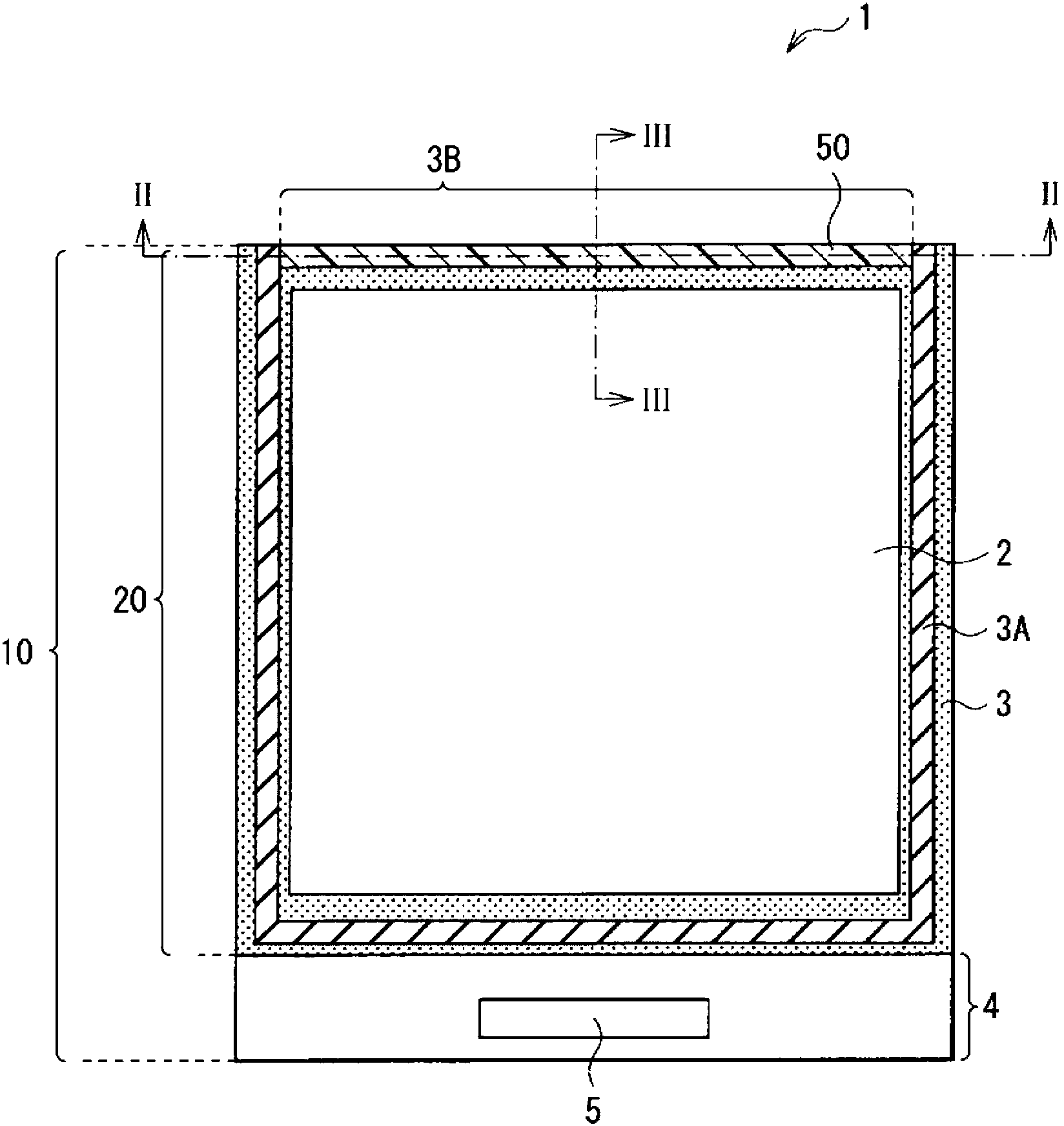
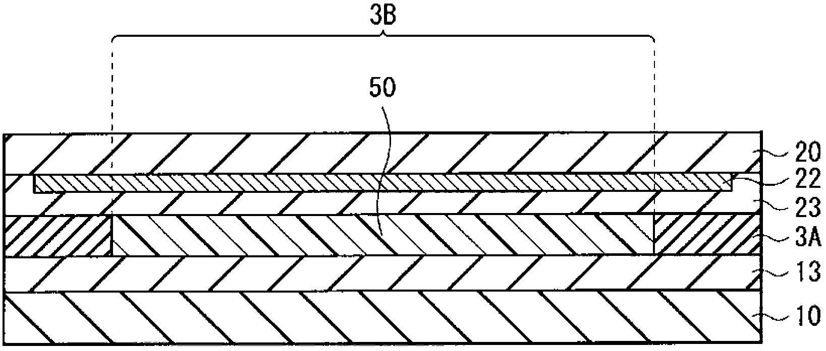
[0061] figure 1 The overall configuration of the liquid crystal display device according to the first embodiment of the present invention is shown. This liquid crystal display device 1 is used, for example, in a mobile phone or a smartphone. The liquid crystal display device 1 has a display portion 2 and a frame portion 3 around the display portion 2 .

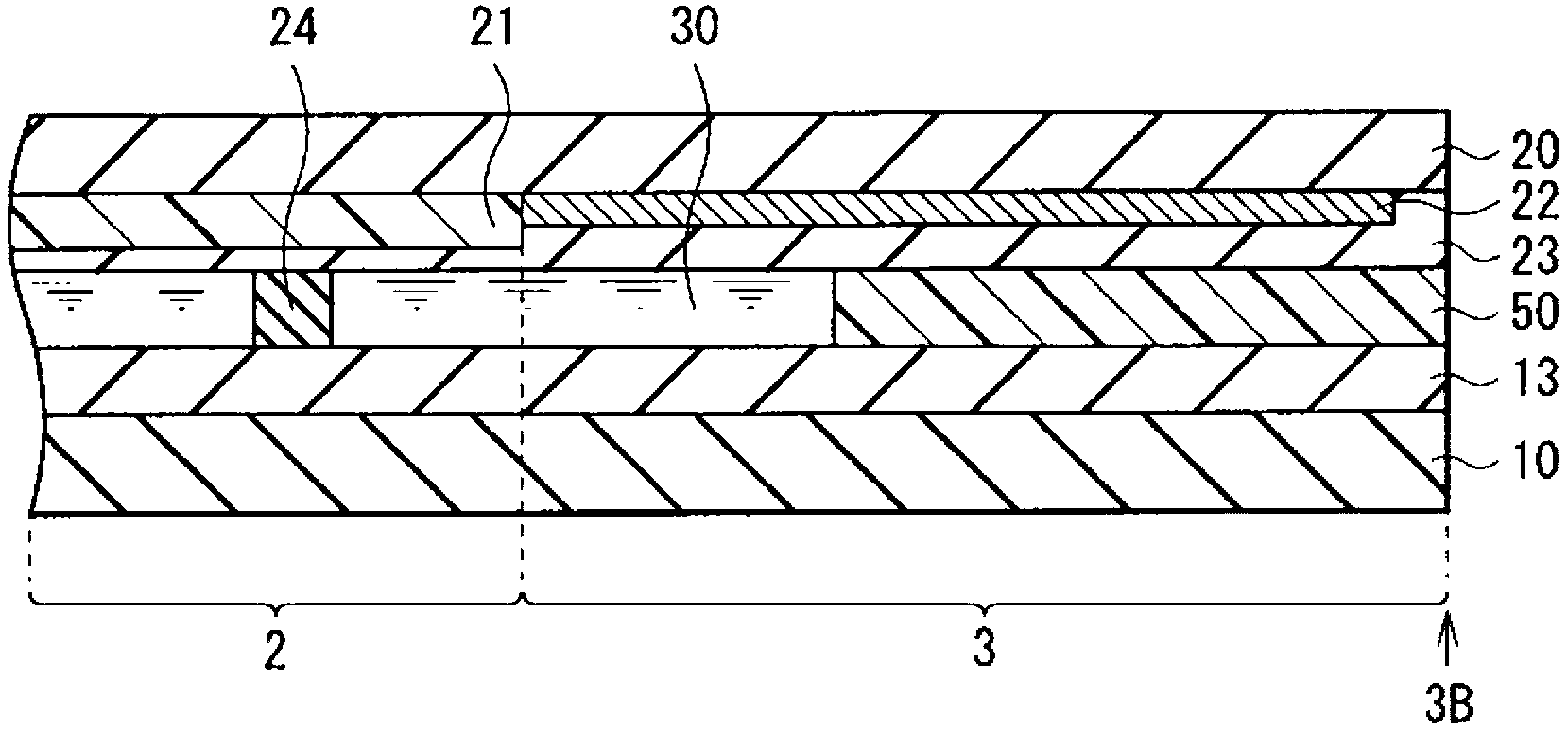
[0062] The display section 2 has a liquid crystal layer 30 ( figure 1 not shown, see image 3 ), the paired substrates (the first substrate 10 and the second substrate 20 ) are made of glass, for example. In the display section 2, a plurality of pixels (not shown) formed of liquid crystal display elements are arranged in a matrix.

[0063] The frame portion 3 is a frame-like area surrounding the display portion 2 at peripheral portions of the first substrate 10 and the second substrate 20 . In the frame portion 3 , a seal frame 3A is mainly composed of thermosetting resin, for example, and is provided to surround the disp...

no. 2 example )

[0083] Image 6 A plan configuration of a liquid crystal display device 1A according to a second embodiment of the present invention is shown. Figure 7 shows along the Image 6 The cross-sectional structure of the VII-VII line, while Figure 8 shows along the Image 6 The cross-sectional structure of the VIII-VIII line. In the present embodiment, the flow of the sealing material 50 is controlled by providing the overflow structure 40 between the inlet 3B and the display portion 2 . Other than that, this liquid crystal display device 1A has the same configuration, operation and effects as those of the first embodiment.

[0084] The overflow structure 40 has, for example, a planar shape with three sides forming a rectangle, and is formed along one side of the display portion 2 (in Image 6 The upper side of the middle) is composed of a straight part and a curved part at both ends of the straight part. The gap 41 is made between the curved portions at both ends of the over...

example 1)

[0104] Figure 12 A plan configuration of a liquid crystal display device 1B according to Modification Example 1 is shown. This liquid crystal display device 1B has the same construction, operation and effect as the second embodiment except that the overflow structure 40 is provided in a straight line along the upper side of the display portion 2, and can be manufactured similarly to the second embodiment.


PUM


Abstract

The present invention discloses a liquid crystal display device and a manufacturing method thereof. The liquid crystal display device comprises: a display portion having a liquid crystal layer between paired substrates; and a frame portion which is disposed in the peripheral portion of the paired substrates. The frame portion has an inlet for injecting liquid crystal, and the inlet is arranged in a continuous linear manner. The manufacturing method for the liquid crystal display device comprises: providing the inlet in a continuous linear manner in the frame portion; and injecting the liquid crystal from the inlet into the gap between the paired substrates.

Description

technical field [0001] The present invention relates to a liquid crystal display device suitable for reducing the frame size and its manufacturing method. Background technique [0002] In the liquid crystal display device, the seal frame is provided outside the display portion. After the liquid crystal is injected from the inlet of the sealing frame, a sealing material is filled in the inlet, and the inlet is closed. If the frame size becomes small, filling control of the sealing material becomes difficult, and the sealing material may affect the display area. Therefore, when the frame size is small, the method of dropping liquid crystals is advantageous, for example, as described in Japanese Patent Laid-Open No. 2005-338886. [0003] However, the method employing dripping causes problems such as the following: new equipment is required; the width of the seal frame cannot be reduced; and the liquid crystal is in contact with the seal frame before baking and thus has a larg...

Claims


Application Information

Patent Timeline
IPC IPC(8): G02F1/1339G02F1/1341G02F1/1333
CPCG02F1/1333G02F1/1341G02F1/1339
Inventor 小糸健夫高间大辅
Owner JAPAN DISPLAY INC
Why Eureka
Try Eureka